Computer Graphics with OpenGL
Table of Contents
- 1. Computer Graphics
- 1.1. Computer Graphics Overview [DRAFT]
- 1.2. GPU Accelerated Computer Graphics APIs
- 1.3. OpenGL Documentation
- 1.4. Terminology related to OpenGL and Computer Graphics
- 1.5. OpenGL companion libraries and 3D models
- 1.6. Legacy/Obsolete OpenGL APIs / Subroutines
- 1.7. Operating System Specific
- 1.8. Computer Graphics Math
- 1.8.1. Overview
- 1.8.2. Vector Algebra
- 1.8.3. Affine Transforms
- 1.8.4. 2D Canonical Affine Transforms
- 1.8.5. 2D Window to Viewport transform
- 1.8.6. 3D Affine Transforms
- 1.8.7. Rotation Matrix and Rodrigues' Rotation Formula
- 1.8.8. Camera View Transform
- 1.8.9. Camera Projection Transform
- 1.8.10. Concatenating Affine Transforms
- 1.8.11. 3D Scene Coordinate Transformations
- 1.8.12. 2D Scene Transforms
- 1.8.13. Rotation Matrix and DCM - Direction Cosine Matrix
- 1.8.14. Default Coordinate Systems
- 1.8.15. Column-Major X Row-major Matrices
- 1.8.16. Quaternions
- 1.8.17. Quaternions - Combining Scale and Position
- 1.8.18. Quaternion in Julia Language
- 1.9. Drawing Primitives
- 1.10. Library GLM - OpenGL Mathematics
- 1.11. [DRAFT] Debugging Computer Graphics Code
- 1.12. Minimal C++ GLFW project
- 1.13. Minimal Dlang (D) GLFW and XMake project
- 1.14. Minimal SDL project
- 1.15. Minimal Qt5 OpenGL project
- 1.16. Minimal WebGL-OpenGL project
- 1.17. Loading OpenGL without Glew
- 1.18. 2D - using VAO
- 1.19. 2D - using shaders
- 1.20. 2D - Chart with orthographic projection
- 1.21. 2D - IBO - Index Buffer Object
- 1.22. 3D - Rotating cube/box
- 1.23. 3D - WebGL 3D Scene with grid and cube
- 1.24. 3D - Quaternion
- 1.25. 3D - Surface wireframe chart
- 1.26. 3D - 3D model loading with illumination
1 Computer Graphics
1.1 Computer Graphics Overview [DRAFT]
Motivation
Outline of common computer graphics applications and a motivation for the study of this field.
- 2D and 3D Games
- Virtual Reality
- Cartography
- Topography
- Charts and plotting
- Scientific Visualization
- Data visualization
- Medical Images
- Physics and engineering simulations.
- Implementation of CAD (Computer Aided Design) systems
- Animation. See Pixar company that created many movies using computer graphics.
Books
- OpenGL Programming Guide: The Official Guide to Learning OpenG, Version 4.3
- Note: Official Modern OpenGL documentation with lots of details and explanations.
- Advanced Graphics Programming Using OpenGL - (The Morgan Kaufmann
Series in Computer Graphics) 1st Edition
- Brief: "This book brings the graphics programmer beyond the basics and introduces them to advanced knowledge that is hard to obtain outside of an intensive CG work environment. The book is about graphics techniques―those that don’t require esoteric hardware or custom graphics libraries―that are written in a comprehensive style and do useful things. It covers graphics that are not covered well in your old graphics textbook. But it also goes further, teaching you how to apply those techniques in real world applications, filling real world needs."
- Note: Contains useful notes about data visualization and CAD implementations.
- Interactive Computer Graphics: A Top-Down Approach With Shader-Based Opengl - 6th Edition
- Brief: "This book is suitable for undergraduate students in computer science and engineering, for students in other disciplines who have good programming skills, and for professionals. Computer animation and graphics–once rare, complicated, and comparatively expensive–are now prevalent in everyday life from the computer screen to the movie screen. Interactive Computer Graphics: A Top-Down Approach with Shader-Based OpenGL, 6e, is the only introduction to computer graphics text for undergraduates that fully integrates OpenGL 3.1 and emphasizes application-based programming. Using C and C++, the top-down, programming-oriented approach allows for coverage of engaging 3D material early in the text so readers immediately begin to create their own 3D graphics. Low-level algorithms (for topics such as line drawing and filling polygons) are presented after readers learn to create graphics."
- OpenGL Super Bible [ONLINE]
Videos - Related to Computer Graphics
- Tutorial 9 - Coordinate Systems in OpenGL [BEST]
- The True Power of the Matrix (Transformations in Graphics) - Computerphile
- A universe of Triangles - Computerphile
- VOX - Why video games are made of tiny triangles
- VOX - Why gamers use WASD to move
- The World's Most Famous Teapot: The Utah Teapot
- Computer - Breaking the Utah Teapot - 1989 (10 minutes)
- "Alan Norton's groundbreaking graphics work from 1989 done at IBM Research. The Utah Teapot was the common object used within graphics research. Alan's notion was to tease the community by breaking their common object. This is my video of Alan describing his research. It was a wondrous experience to work with him. The video was for my international multimedia magazine, a project I received after convincing an IBM Research VP to let me do something other than language research based on my fandom music video making."
- How a Teapot Revolutionized Computer Graphics (2:41 minutes)
- "Once upon a time, the field of computer graphics was just getting started, and a simple teapot helped researchers develop rendering techniques."
- How Rendering Graphics Works in Games! (6:24 minutes)
- "Going all the way from the bits of vertex coordinates to the rasterizing of pixels, let's learn how rendering graphics works!"
- CPU vs GPU (What's the Difference?) - Computerphile (6:38 minutes)
- "What does a GPU do differently to a CPU and why don't we use them for everything? First of a series from Jem Davies, VP of Technology at ARM."
Communities
- https://www.gamedev.net/
- https://forum.freegamedev.net/
- https://gamedev.stackexchange.com/
- https://old.reddit.com/r/gamedev/
- https://old.reddit.com/r/webgl/
- https://old.reddit.com/r/opengl/
- https://old.reddit.com/r/vulkan/
- https://old.reddit.com/r/GraphicsProgramming
- https://old.reddit.com/r/raytracing
- https://old.reddit.com/r/linux_gaming/
- https://old.reddit.com/r/VFIO/ (Virtualization GPU passthrough.)
1.2 GPU Accelerated Computer Graphics APIs
Native Graphics APIs (exposed as C-subroutines)
- OpenGL (Khronos Group) - Main OpenGL specification
- => Open standard, cross-platform and vendor-independent API for rendering 2D or 3D computer graphics with GPU (Graphics Processing Unit) acceleration. OpenGL can be used for implementing computer graphics, games, scientific vizualization, virtual reality and CADs - Computer Aided Design software. OpenGL API specificiation is maintained as an open-standard by the Krhonos Group industry consortium.
- => OpenGL has two modes, immediate mode (a.k.a fixed-function pipeline, legacy-OpenGL) which is being depreacted, and retained mode (modern OpenGL) that delivers more performance and is based on buffer-objects and shaders.
- => OpenGL Official Specification: Khronos OpenGL® Registry
- OpenGL ES (Khronos Group)
- => OpenGL for embedded systems, mobile devices and touch screen devices and so on. This API (Application Programming Interface) is widely used by many mobile games.
- => Similar to OpenGL specfication, but supports only the retained-mode. OpenGL ES does not support immediate-mode. As a result, calls to legacy OpenGL subroutines such as glBegin(), glEnd(), glRotate(), glTranslate(), …, are not supported.
- Vulkan_(Khronos Group)
- => Graphics API with GPU acceleration that provides more low-level GPU control and less overhead than OpenGL. This API is designed for taking more advantag of multi-core CPU architectures and performing tasks in parallel.
- DirectX / Direct3D (Microsoft inc.) - Windows-only
- => Microsoft's graphics API for accessing the GPU hardware. It is only available on operating systems based Windows-NT kernel and Windows-CE kernel (embedded version of Windows-NT).
- Metal (Apple inc.)
- => Apple-only API for rendering 2D or 3D computer graphics with GPU acceleration. This API is available only on iOS and MacOSX operating systems. On iOS and MacOSX, Apple is deprecating and phasing out OpenGL in favor of its own API.
Web Computer Graphics APIs (exposed as Javascript/ECMAScript subroutines)
- WebGL (Khronos Group) / Html5 API
- => Based on OpenGL ES and implemented by major web browsers. Unlike OpenGL or OpenGL ES, which are exposed via C subroutines, WebGL is exposed to calling codes via JavaScript (ECMAScript) and Html5 canvas.
- => Note: This API does not support OpenGL immediate-mode or legacy OpenGL. WebGL only supports retained-mode.
- WebGPU (W3C Consortium) - Upcoming Html5 standard.
- => Upcoming graphics API for web browser, based on Vulkan, Metal and DirectX which intends to deliver more low level GPU control and higher performance. Unlike WebGL, this API is not a direct port of any native graphics API such as Vulkan, Metal and DirectX.
- WebGPU - Editor’s Draft
- Implementation Status · gpuweb/gpuweb Wiki · GitHub
- GitHub - gpuweb/gpuweb: Where the GPU for the Web work happens!
- Point of WebGPU on native
- A Taste of WebGPU in Firefox - Mozilla Hacks - the Web developer blog
Further Reading
General:
- GitHub - KhronosGroup/MoltenVK
- "MoltenVK is a Vulkan Portability implementation. It layers a subset of the high-performance, industry-standard Vulkan graphics and compute API over Apple's Metal graphics framework, enabling Vulkan applications to run on iOS and macOS."
- Doom benchmarks return: Vulkan vs. OpenGL | PC Gamer
- Vulkan for Linux Users – Linux Hint
- What can Vulkan do specifically that OpenGL 4.6+ cannot? - Stack
- design - OpenGL and global state - Software Engineering Stack Exchange
- ZINK - OpenGL Implementation on Top of Vulkan
GPU Listing:
- Mali GPU - GPU used by most ARM-based mobile devices with ARM integrated GPUs.
- List of Nvidia graphics processing units
- List of AMD graphics processing units
- The Decline of Computers as a General Purpose Technology - ACM Communications.
- Devices - Vulkan Hardware Database by Sascha Willems
- https://egpu.io/best-egpu-buyers-guide/
Image Resolution DPI, PPI and so on:
- Resolution Independence
- Pixel Density
- Vector Graphics
- SVG - Scalable Vector Graphics
- Comparison of Graphic File Formats
- Retina Display - Apple
- Making sense of DPI, PPI, Megapixels and Resolution - Atiz Innovation
- What Resolution Should Your Images Be?
- Pixelscalculator - Convert DPI / PPI to Pixels and cmm, cm, inches
- PPI - Calculator (Pixels Per Inch)
1.3 OpenGL Documentation
OpenGL:
- docs.gl [BEST]
- Allows searching and quickly browsing the OpenGL documentation.
- https://www.opengl.org/
- Microsoft Windows OpenGL Implementation - WGL
- Khronos OpenGL® Registry
- OpenGL Official Specification.
- Core Language (GLSL) - OpenGL Wiki / Khronos Group
- Official Documentation of OpenGL shading language.
- Data Type (GLSL) - OpenGL Wiki / Khronos Group
- Data types of GLSL - OpenGL Shading Language.
- The Book of Shaders - (Patricio Gonzalez and Jen Love)
- OpenGL ES SDK for Android Documentation (ARM Company)
- OpenGL Registry (Khronos Group) / glEnable() => Documentation of OpenGL glEnable options, which sets the capabilities.
- Common Mistakes (Khronos Group) =>> Useful for debugging.
- 3D Maths Cheat Sheet - Reference Card for computer graphics linear algebra. (homogeneous coordinates, rotation matrices, translation matrices and etc.)
WebGL:
- WebGL Overview - The Khronos Group Inc
- "WebGL is a cross-platform, royalty-free web standard for a low-level 3D graphics API based on OpenGL ES, exposed to ECMAScript via the HTML5 Canvas element. Developers familiar with OpenGL ES 2.0 will recognize WebGL as a Shader-based API using GLSL, with constructs that are semantically similar to those of the underlying OpenGL ES API. It stays very close to the OpenGL ES specification, with some concessions made for what developers expect out of memory-managed languages such as JavaScript. WebGL 1.0 exposes the OpenGL ES 2.0 feature set; WebGL 2.0 exposes the OpenGL ES 3.0 API."
- WebGL tutorial - Web APIs | MDN
- Getting started with WebGL - Web APIs | MDN - WebGL Documentation.
- WebGL Fundamentals
1.4 Terminology related to OpenGL and Computer Graphics
- SIGGRAPH - international Association for Computing Machinery's Special Interest Group on Computer Graphics and Interactive Technique.
- API - Application Programming Interface
- Khronos Group - Industry consortium that takes care of OpenGL and Vulkan standards and specifications.
- SGI - Silicon Graphics International - Company which developed first version of OpenGL. It was known for its SGI workstations.
- OpenGL - Open Graphics Library
- OpenGL Context
- GLEW - OpenGL Extension Wrangler
- ARB - OpenGL Architecture Review Board
- OpenGL Immediate Mode (Fixed-Function Pipeline, Legacy OpenGL)
- Also known as: Legacy OpenGL, Fixed-Function Pipeline
- Drawing is mostly performed without storing data on GPU and by using subroutines calls to glScale(), glRotate(), glPush(), glPop(), glTranslate(), glBegin(), glEnd() and so on.
- Immediate-mode is not supported by OpenGL ES or WebGL.
- See: Fixed Function Pipeline - OpenGL Wiki
- OpenGL retained mode (Programmable Pipeline, Modern OpenGL)
- Also known as: Modern OpenGL, Programmable Pipeline
- New and modern OpenGL API => Drawing is performed by storing data on the GPU via VBO (Vertex Buffer Objects) and by using shaders, programs that runs on GPU, for performing geometric vertex transformations, color and texturing computations.
- More peformant than immediate-mode as the data is not sent to the GPU every frame.
- GPU - Graphics Processing Unit
- iGPU - Integrated GPU - The GPU is in the same processor chip silicon die. Most mobile GPUs are integrated. Most desktop computers also have dedicated GPUs built in the same chip as the CPU cores. This type of GPU is enough for most common tasks such as lightweight games, 2D games and watching youtube videos, but they are not suitable for heavy AAA (triple-A) games or for running CAD applications. Note: Most server-grade processor IC (Integrated Circuits), such as Intel Xeon lacks integrated GPU.
- dGPU - Dedicated GPU - GPU available as a separated card and connected to the motherboard via PCI connection. They are suitable for triple-A games and GPGPU (General Purpose GPU Computing). The biggest manufacturers of those GPUs are Nvidia and AMD (Advanced Micro Devices).
- eGPU - External GPU - GPU external to the motherboard and often connected via thunderbolt cable. External GPUs can be used on laptop machines, that often lack enough space for installing a dedicated GPU. Disadvantage: only newer motherboards have support for thunderbolt cables.
- GPGPU - General Purpose Computing on GPU
- APIs: OpenCL, Cuda, and so on.
- Parallel non-graphics computations on GPU. GPGPU APIs take advantage of GPU parallel computing features for high performance computing.
- AAA - Triple-A games.
- DSA - Direct State Access
- Vertex - 2D or 3D coordinates representing a point in the space.
- DOF - Degrees Of Freedom
- 2D - 2 dimensions (plane) / 2 coordinates (X, Y)
- 3D - 3 dimensions (space) / 3 coordinates (X, Y, Z)
- Homogenous Coordinate - Coordinate system using an extra dimension
for encoding translation coordinate transformation in the same way
as rotation matrices transformations.
- 2D homogeneous coordinates: (X, Y, W = 1)
- 3D homogeneous coordinates: (X, Y, Z, W = 1)
- NDC - Normalized Device Coordinate
- Default coordinates used by OpenGL (-1.0 to 1.0) for each axis. Any vertex that falls out of this range will not be visible on the screen.
- MCS - Model Coordinate System
- CTM - Current Transform Matrix
- Buffer Object
- VBO - Vertex Buffer Object
- VAO - Vertex Array Object
- FBO - Framebuffer Object
- IBO - Index Buffer Object
- UBO - Uniform Buffer Object
- FPS - Frame Per Seconds
- Shader - Program that runs on the GPU and performs vertex computations such as coordinate transformations (matrix multiplications), colors and texture computations.
- GLSL - OpenGL shading programming language - for performing computer graphics calculations on the GPU hardware.
- HLSL (High-Level Shader Language) - Microsft's DirectX shading language.
- COP - Center Of Projection
- CAD - Computer Aided Design
- CAM - Computer Aided Manufacturing
- CSG - Constructive Solid Geometry
- Computer Graphics Data Structures
- Mesh
- Nurb
- Voxel
- Quad tree
- Octo tree
- DEM - Digital Elevation Model
- Common Mesh File Formats (Standardized file formats for mesh storage)
- .obj File - ASCII text file format for mesh storage.
- .ply File - Polygon File Format
- .vrml File - VRM XML file format created by the W3C consortium.
- .blend File - Blender File format
- Article Related to Meshes
- Resolution
- PPI - Pixels Per Inch
- DPI - Dots Per Inch
- Display Types
- CRT - Cathode Ray Tube
- LCD - Liquid Crtystal Display
- PDP - Plasma Display Panel
- OLED
1.5 OpenGL companion libraries and 3D models
1.5.1 OpenGL Companion Libraries
OpenGL Loaders: [ESSENTIAL]
- Libraries that abstracts OpenGL function pointers loading in a platform-independent way.
- GLEW - OpenGL Extension Wrangler [MOST USED]
- "The OpenGL Extension Wrangler Library (GLEW) is a cross-platform open-source C/C++ extension loading library. GLEW provides efficient run-time mechanisms for determining which OpenGL extensions are supported on the target platform. OpenGL core and extension functionality is exposed in a single header file. GLEW has been tested on a variety of operating systems, including Windows, Linux, Mac OS X, FreeBSD, Irix, and Solaris."
- GLAD - [MOST-USED] Multi-Language GL/GLES/EGL/GLX/WGL Loader-Generator based on the official specs.
- GitHub - cginternals/glbinding
- "A C++ binding for the OpenGL API, generated using the gl.xml specification."
- GitHub - anholt/libepoxy
- "Epoxy is a library for handling OpenGL function pointer management for you."
- GitHub - imakris/glatter
- "An OpenGL loading library, with support for GL, GLES, EGL, GLX and WGL"
- Galogen OpenGL Loader Generator
- "Galogen is an OpenGL loader generator. Given an API version and a list of extensions, Galogen will produce corresponding headers and code that load the exact OpenGL entry points you need. The produced code can then be used directly by your C or C++ application, without having to link against any additional libraries."
- GitHub - SFML/SFML-glLoadGen
- Customized glLoadGen for SFML
Window System Abstraction
Libraries for window systems, event handling and OpenGL context abstraction: [ESSENTIAL]
- Abstract platform-specific window system and event handling.
- GLFW [BEST] [MOST-USED]
- C library that provides graphics windows for OpenGL, Vulkan, OpenGL ES and deals with event handling.
- SDL (Simple Direct Media Layer) [BEST] [MOST-USED]
- Cross-platform C library that provides windows and event handling for many computer graphics APIs such as OpenGL, Vulkan and DirectX. SLD also has facilities for dealing with audio, joystick, CD-ROM, network and threads.
- SFML (Simple and Fast Multimedia Library) [MOST-USED]
- "SFML provides a simple interface to the various components of your PC, to ease the development of games and multimedia applications. It is composed of five modules: system, window, graphics, audio and network."
- GLUT (FreeGlut) - OpenGL Utility Toolkit
- Deals with window creation, OpenGL initialization, event handling and so on.
- Docs: https://www.glfw.org/documentation.html
Graphics Math Libraries
OpenGL Math and Computer Graphics Math: [ESSENTIAL]
- GLM (OpenGL Mathematics Library) [MOST-USED]
- Source code: https://github.com/g-truc/glm
- Header-only C++ library that provides classes for computer graphics mathematics such as: 2D, 3D and homogeneous coordinate vector; 2D, 3D and homogeneous coordinate transformation matrices; quaternions and subroutines for computing camera, perspective or orthogonal transformation matrices.
- GitHub - Kazade/kazmath - A C math library targeted at games
- "Kazmath is a simple 3D maths library written in C. It was initially coded for use in my book, Beginning OpenGL Game Programming - Second edition, but rapidly gained a life of its own. Kazmath is now used by many different projects, and apparently is used in 25% of the worlds mobile games (yeah, I don't believe it either - but it's used in Cocos2d-x)."
- GitHub - recp/cglm - Highly Optimized Graphics Math (glm) for C
- See: GitHub - chunkyguy/Math-Library-Test - A comparison of the various major math libraries for speed and ease of use.
Image Loading for texture
- GLI - OpenGL Image
- "OpenGL Image (GLI) is a header only C++ image library for graphics software. GLI provides classes and functions to load image files (KTX and DDS), facilitate graphics APIs texture creation, compare textures, access texture texels, sample textures, convert textures, generate mipmaps, etc."
- smoked-herring/sail - Squirrel Abstract Image Library
- "SAIL is a format-agnostic cross-platform image decoding library providing rich APIs, from one-liners to complex use cases with custom I/O sources. It enables a client to read and write static, animated, multi-paged images along with their meta data and ICC profiles."
- Note: Supports APNG, BMP, GIF, JPEG, PNG and TIFF image formats.
- stb_image.h - single-file header-only C library for loading images from several file formats including, jpeg, bmp, tga, ppm, pgm, gif and so on.
- SOIL - Simple OpenGL Image Library
- "SOIL is a tiny C library used primarily for uploading textures into OpenGL. It is based on stb_image version 1.16, the public domain code from Sean Barrett (found here). It has been extended to load TGA and DDS files, and to perform common functions needed in loading OpenGL textures. SOIL can also be used to save and load images in a variety of formats."
- freeimage
- "FreeImage is an Open Source library project for developers who would like to support popular graphics image formats like PNG, BMP, JPEG, TIFF and others as needed by today's multimedia applications. FreeImage is easy to use, fast, multithreading safe, compatible with all 32-bit or 64-bit versions of Windows, and cross-platform (works both with Linux and Mac OS X)."
- gldraw
- "With glraw you can preconvert your texture assets and load them without the need of any image library. The generated raw files can easily be read. For this, glraw also provides a minimal Raw-File reader that you can either source-copy or integrate as C++ library into your project. Image to OpenGL texture conversion can be done either by glraws command line interface, e.g., within an existing tool-chain, or at run-time with glraw linked as asset library (requires linking Qt)."
- lodepng
- "LodePNG is a PNG image decoder and encoder, all in one, no dependency or linkage to zlib or libpng required. It's made for C (ISO C90), and has a C++ wrapper with a more convenient interface on top."
- libpng
- "libpng is the official PNG reference library. It supports almost all PNG features, is extensible, and has been extensively tested for over 23 years. The home site for development versions (i.e., may be buggy or subject to change or include experimental features) is https://libpng.sourceforge.io/, and the place to go for questions about the library is the png-mng-implement mailing list. libpng is available as ANSI C (C89) source code and requires zlib 1.0.4 or later (1.2.5 or later recommended for performance and security reasons). The current public release, libpng 1.6.37, fixes the use-after-free security vulnerability noted below, as well as an ARM NEON memory leak in the palette-to-RGB(A) expansion code (png_do_expand_palette())."
- libspng
- "libspng (simple png) is a C library for reading and writing Portable Network Graphics (PNG) format files with a focus on security and ease of use. It is licensed under the BSD 2-clause “Simplified” License."
- IJG - Indepedent JPEG Group
- "IJG is an informal group that writes and distributes a widely used free library for JPEG image compression. The first version was released on 7-Oct-1991. The current version is release 9d of 12-Jan-2020. This is a stable and solid foundation for many application's JPEG support. You can find our original code and some supporting documentation in the directory files. There is a Windows format package in zip archive format jpegsr9d.zip and a Unix format package in tar.gz archive format jpegsrc.v9d.tar.gz. A collection of modified versions with adaptions and error fixes for system maintenance is available on jpegclub.org in the directory support."
Asset/Object Loaders - Mesh Importing Libraries [ESSENTIAL]
Object loader / Asset import libraries:
- Assimp - The Open-Asset-Import Library [MOST-USED]
- "The Open Asset Import Library (short name: Assimp) is a portable Open-Source library to import various well-known 3D model formats in a uniform manner. The most recent version also knows how to export 3d files and is therefore suitable as a general-purpose 3D model converter. See the feature-list."
- Note: Allows importing blender-generated models/assets in OpenGL.
- Repository: https://github.com/assimp/assimp
- See: https://www.khronos.org/opengl/wiki/Tools/Open_Asset_Import
- OBJ-Loader
- "OBJ Loader is a simple, header only, .obj model file loader that will take in a path to a file, load it into the Loader class object, then allow you to get the data from each mesh loaded. This will load each mesh within the model with the corresponding data such as vertices, indices, and material. Plus a large array of vertices, indices and materials which you can do whatever you want with."
- tinyobjloader/tinyobjloader
- "Tiny but powerful single file wavefront obj loader written in C++03. No dependency except for C++ STL. It can parse over 10M polygons with moderate memory and time. tinyobjloader is good for embedding .obj loader to your (global illumination) renderer ;-)."
- codelibs/libdxfrw
- "C++ library to read and write DXF/DWG (Autocad file format) files. - libdxfrw is a free C++ library to read and write DXF files in both formats, ascii and binary form. Also can read DWG files from R14 to the last V2015. It is licensed under the terms of the GNU General Public License version 2 (or at you option any later version)."
Text and Font Rendering
- The FreeType Project
- Brief: "It is written in C, designed to be small, efficient, highly customizable, and portable while capable of producing high-quality output (glyph images) of most vector and bitmap font formats."
- OGLFT: OpenGL-FreeType Library
- Brief: "This C++ library supplies an interface between the fonts on your system and an OpenGL or Mesa application. It uses the excellent FreeType library to read font faces from their files and renders text strings as OpenGL primitives."
- GitHub - vallentin/glText - [HEADER-ONLY-LIBRARY]
- Brief: "glText is a simple cross-platform single header text rendering library for OpenGL. glText requires no additional files (such as fonts or textures) for drawing text, everything comes pre-packed in the header."
- GitHub - MartinPerry/OpenGL-Font-Rendering
- Brief: "Rendering UNICODE fonts with OpenGL This library is still work-in-progress. This is a working beta version."
- libdrawtext - OpenGL text rendering library
- Brief: "Libdrawtext uses freetype2 for glyph rasterization. If you would rather avoid having freetype2 as a dependency, you can optionally compile libdrawtext without it, and use pre-rendered glyphmaps. Glyphmaps can be generated by the included font2glyphmap tool, or by calling dtx_save_glyphmap."
- GitHub - codetiger/Font23D - Convert any text to a 3d mesh using any font style
- Brief: "Font23D is a C++ library for creating a 3d mesh of any Text in the given True type font."
C++ Wrappers
- OGplus - Self described as C++ Wrapper for modern OpengL.
- Brief: "OGLplus is a header-only library which implements a thin object-oriented facade over the OpenGL® (version 3 and higher) C-language API. It provides wrappers which automate resource and object management and make the use of OpenGL in C++ safer and easier."
- Repository: https://github.com/matus-chochlik/oglplu2
- Oglwrap
- Brief: "Oglwrap is a lightweight, cross-platform, object-oriented, header-only C++ wrapper for modern (2.1+) OpenGL, that focuses on preventing most of the trivial OpenGL errors, and giving as much debug information about the other errors, as possible."
- Globjects - globjects is a cross-platform C++ wrapper for OpenGL
API objects
- Brief: "globjects provides object-oriented interfaces to the OpenGL API (3.0 and higher). It reduces the amount of OpenGL code required for rendering and facilitates coherent OpenGL use by means of an additional abstraction layer to glbinding and GLM. Common rendering tasks and processes are automated and missing features of specific OpenGL drivers are partially simulated or even emulated at run-time."
Form-based Graphical User Interface
- Dear imgui
- Brief: "Dear ImGui is a bloat-free graphical user interface library for C++. It outputs optimized vertex buffers that you can render anytime in your 3D-pipeline enabled application. It is fast, portable, renderer agnostic and self-contained (no external dependencies)."
- See: An introduction to Dear Imgui Library
Non-categorized / Miscellaneous
- bkaradzic/bgfx - "Bring Your Own Engine/Framework"
- Brief: Library for providing a unified interface to many GPU accelerated graphics APIs, including OpenGL, OpenGL ES, WebGL, WebGPU (W3C consoritum), DirectX (Microsoft), Metal (Apple) and Vulkan.
- Note: This library also abstracts the shading language, a subset of GLSL OpenGL, that works with all mentioned GPU accelerated rendering backends.
- Documentation:
- Community:
- See:
- Shader Debugging for BGFX Rendering Engine (Kai Wang)
- GLSDK - Unofficial OpenGL Software Development Kit
- Brief: "The Unofficial OpenGL Software Development Kit is a collection of libraries and utilities that will help you get started working with OpenGL. It provides a unified, cross-platform build system to make compiling the disparate libraries easier. Many of the components of the SDK are C++ libraries. Each component of the SDK specifies the terms under which they are distributed. All licenses used by components are approximately like the MIT license in permissivity. The parts of the SDK responsible for maintaining the build, as well as all examples, are distributed under the MIT License."
- NXPmicro/gtec-demo-framework
- "A multi-platform framework for fast and easy demo development. The framework abstracts away all the boilerplate & OS specific code of allocating windows, creating the context, texture loading, shader compilation, render loop, animation ticks, benchmarking graph overlays etc. Thereby allowing the demo/benchmark developer to focus on writing the actual 'demo' code. Therefore demos can be developed on PC or Android where the tool chain and debug facilities often allows for faster turnaround time and then compiled and deployed without code changes for other supported platforms. The framework also allows for ‘real’ comparative benchmarks between the different OS and windowing systems, since the exact same demo/benchmark code run on all of them."
- Supported Operating Systems: Android NDK; Linux with various windowing systems (Yocto); Ubuntu 18.04; Windows 7+
1.5.2 WebGL Companion Libraries
WebGL Companion Libraries: (OpenGL on the WEB)
- glMatrix - GLM math library ported to Javascript. Computer graphics math library, similar to OpenGL GLM math library.
- Math.GL - "math.gl is JavaScript math library focused on geospatial and 3D use cases, designed as a composable, modular toolbox. math.gl provides a core module with classic vector and matrix classes, and a suite of optional modules implementing various aspects of geospatial and 3D math. While the math.gl is highly optimized for use with the WebGL and WebGPU APIs, math.gl itself has no WebGL dependencies."
- GLM-JS - "glm-js is an experimental JavaScript implementation of the OpenGL Mathematics (GLM) C++ Library."
- Three.JS - High level wrapper library around WebGL, that provides many high level features that includes: camera objects; scene graphs; geometry; perspective; forward kinematics, inverse kinematics; graphics math library containing, matrices, vectors, quaternions; image loaders; animation and more.
- phoria.js - [NOT WEBGL] "JavaScript library for simple 3D graphics
and visualisation on a HTML5 canvas 2D renderer. It does not use
WebGL. Works on all HTML5 browsers, including desktop, iOS and
Android."
- Note: It does use WebGL, but it is an interesting codebase about computer graphics algorithms implementation.
1.5.3 Sample 3D Models Repositories
- https://free3d.com/3d-models/obj-file
- common-3d-test-models
- "This is a repository containing common 3D test models in original format with original source if known. While a similar list exists on wikipedia, it does not host the actual models and is incomplete."
- https://github.com/pichiliani/ModelsOBJ
- "ModelsOBJ - .OBJ files with free 3D models (CC license or royalty free)"
- Gist - cube.obj
- Gist containing a cube 3D model obj file with vertices and normals.
- Teapot.obj - Teapot common 3D test model with normals.
Note: 3D models can be created using applications such as Blender, MeshlLab, Autodesk Maya, Solidworks and so on.
See also:
- List of common 3D test models
- Smoothing .obj 3D models (Guru Mulay)
Obj File Documentation:
- https://docs.fileformat.com/3d/obj/
- Weverfron OBJ File Format - Library of Congress
1.5.4 See also
- OpenGL Loading Library - OpenGL Wiki / Khronos Group
- Brief: "An OpenGL Loading Library is a library that loads pointers to OpenGL functions at runtime, core as well as extensions. This is required to access functions from OpenGL versions above 1.1 on most platforms. Extension loading libraries also abstracts away the difference between the loading mechanisms on different platforms."
- Load OpenGL Functions - OpenGL Wiki / Khronos Group
- Brief: "Loading OpenGL Functions is an important task for initializing OpenGL after creating an OpenGL context. You are strongly advised to use an OpenGL Loading Library instead of a manual process. However, if you want to know how it works manually, read on."
- Image Libraries - OpenGL Wiki / Khronos Group
- When do I need to use an OpenGL function loader? - Stack Overflow
- KeyJ's Blog : Blog Archive » Modern OpenGL with lcc-win32, the hard way
- Loading OpenGL without GLEW
- Using OpenGL With SDL - LibSDL
- Tutorial1: Creating a Cross Platform OpenGL 3.2 Context in SDL (C / SDL) - OpenGL Wiki
1.6 Legacy/Obsolete OpenGL APIs / Subroutines
The following OpenGL subroutines are from the OpenGL immediate mode (fixed-function pipeline), which are obsolete and should be avoided as they incur on a significant overhead and they lack portability since they are not be available on OpenGL ES.
Note: The best way to check wether a OpenGL subroutine is obsolete is by searching for its name at http://docs.gl/. Subroutines without ES2, ES3 or GL4 hyperlinks are obsolete. For instance, by searching for 'glLight' at this web site, there are no ES2, ES3 or GL4 hyperlinks, which indicates that this subroutine is outdated.
Obsolete Subroutines:
- Vertex:
- => Modern OpenGL replacement: VBO (Vertex Buffer Object) and VAO (Vertex Array Object) and shader program.
- glVertex2f() => 2D coordinate of current vertex
- glVertex3f() => 3D Coordinate of current vertex
- glNormal3f() => Sets the surface normal vector for the current vertex.
- glColor3f() => Sets the color for the current vertex.
- glColor4ub() => Sets the color for the current vertex using RGB in byte format from 0 to 255.
- Begin/End:
- glEnd()
- glBegin()
- Colors
- glColor() => Modern OpenGL replacement: Fragement shader
- glMaterial()
- glVertexPointer()
- Coordinate Transformation
- Modern OpenGL Replacement: shader model matrix uniform variable which is set by the calling code. Since the matrix math (linear algebra) functionality is no longer provided by OpenGL, a third party math library is necessary.
- glLoadIdentity() => Modern OpenGL replacement: glm::mat4(1.0);
- glRotate() => Modern OpenGL replacement: glm::rotate();
- glTranslate() => Modern OpenGL replacement: glm::translate();
- glScale() => Modern OpenGL replacement: glm::scale();
- glRotate3f()
- glMatrixMode()
- glFrustum() => Modern OpenGL replacement: glm::frustum();
- gluLookAt() => Modern OpenGL replacement: glm::lookAt();
- gluPerspective() => Modern OpenGL replacement: glm::perspective();
- glMatrixMode()
- glViewPort()
- glOrtho()
- glMultMatrix()
- Camera affine transforms:
- gluLookAt() => Replacement: glm::lookAt()
- Save Context
- glPop()
- glPush()
- Matrix Stack [DEPRECATED!]
- Modern OpenGL replacement: OpenGL since 3.0, no longer provides a matrix stack. Now the calling code that has to keep track of transformation state.
- glPushMatrix()
- glPopMatrix()
- Light and illumination:
- Modern OpenGL Replacement: Light and illumination model are computed on fragment shader or vertex shader.
- glLight()
- glLightModel()
- glMaterial()
- glNormal3f()
- Miscellaneous / Non Categorized
- glEnableClientState()
- glColorPointer()
- glVertexPointer(*)
- glLight*…
- glMaterial*…
- glDrawPixels()
- glPixelZoom()
- glRasterPos2i()
See:
- glm - Deprecated function replacements
- "The OpenGL 3.0 specification deprecated some features, and most of these have been removed from the OpenGL 3.1 specfication and beyond. GLM provides some replacement functions. Many of these functions come from the GLM_GTC_matrix_transform: Matrix transform functions. extension."
- A Guide to Modern OpenGL Functions
- Matrix stacks in OpenGL deprecated?
- What is the point of the matrix stack in OpenGL?
- OpenGL Matrix Stacks {PDF}
1.7 Operating System Specific
1.7.1 Microsoft Windows NT
Command Line Shortcuts for Troubleshooting
The following applications can be accessed either from command line (cmd.exe shell) or via the shortcut Windows Key + R.
- $ dxdiag => Tool for DirectX and OpenGL diagnostics.
- $ devmgmt.msc => Device manager shortcut.
- $ msinfo32 => View details about hardware.
- $ systeminfo => View summarized information about operating system, hardware, RAM memory, disk space and patches. Note: It only works from command line.
GPU details and OpenGL Implementation Information
- OpenGL Extensions Viewer 6 | realtech VR
- Graphical application that allows viewing details about Vulkan and OpenGL implementation at the current machine.
- Brief: "A reliable software which displays useful information about the current OpenGL 3D accelerator and new Vulkan 3D API. This program displays the vendor name, the version implemented, the renderer name and the extensions of the current OpenGL 3D accelerator."
- GPU Caps View - Geeks3D
- Brief: "A new version of GPU Caps Viewer is available. GPU Caps Viewer is a graphics card / GPU information and monitoring utility that quickly describes the essential capabilities of your GPU including GPU type, amount of VRAM , OpenGL, Vulkan, OpenCL and CUDA API support level."
- GPU Test
- Brief: "GpuTest is a cross-platform (Windows, Linux and Max OS X) GPU stress test and OpenGL benchmark. GpuTest comes with several GPU tests including some popular ones from Windows'world (FurMark or TessMark)."
Setting Default GPU on Windows
1.7.2 Linux-Based Operating Systems
Install OpenGL development dependencies
Install OpenGL development dependencies on Ubuntu or Debian-like distributions:
$ sudo apt-get install -y libgl1-mesa-dev libglu1-mesa-dev freeglut3-dev  libgl1-mesa-dev libxrandr-dev
$ sudo apt-get install -y libxinerama-dev libxcursor-dev libxi-dev
Information about OpenGL and graphics card
Vendor:
 $ >> glxinfo | grep -E "vendor"
server glx vendor string: SGI
client glx vendor string: Mesa Project and SGI
OpenGL vendor string: Intel
Rendering:
 $ >> glxinfo | grep -E "rendering"
direct rendering: Yes
Version:
 $ >> glxinfo | grep -E "version"
server glx version string: 1.4
client glx version string: 1.4
GLX version: 1.4
    Max core profile version: 4.6
    Max compat profile version: 4.6
    Max GLES1 profile version: 1.1
    Max GLES[23] profile version: 3.2
OpenGL core profile version string: 4.6 (Core Profile) Mesa 20.3.2
OpenGL core profile shading language version string: 4.60
OpenGL version string: 4.6 (Compatibility Profile) Mesa 20.3.2
OpenGL shading language version string: 4.60
OpenGL ES profile version string: OpenGL ES 3.2 Mesa 20.3.2
OpenGL ES profile shading language version string: OpenGL ES GLSL ES 3.20
    GL_EXT_shader_implicit_conversions, GL_EXT_shader_integer_mix,
Display:
 $ >> glxinfo | grep -E "display"
name of display: :1
display: :1  screen: 0
1.8 Computer Graphics Math
1.8.1 Overview
Computer graphics math is based on vector algebra, linear algebra and affine transforms. Those concepts are not exclusive to OpenGL, they are essential and universal to all computer graphics APIS - Application Programming Interfaces, including OpenGL, DirectX, Metal, Vulkan, WebGL and html5 canvas.
1.8.2 Vector Algebra
Given 2 3D vectors \(\vec{A} = [ x_A, y_A, z_A ]\) and \(\vec{B} = [ x_B, y_B, z_B ]\) , the following properties can be defined:
Vector Sum
\begin{equation} \vec{C} = \vec{A} + \vec{B} = (x_A + x_B) \hat{i} + (y_A + y_B) \hat{j} + (z_A + z_B) \hat{k} \end{equation}Vector Difference / Subtraction
\begin{equation} \vec{C} = \vec{B} - \vec{A} = (x_B - x_A) \hat{i} + (y_B - y_A) \hat{j} + (z_B - z_A) \hat{k} \end{equation}Vector Norm
The norm or magnitude of A, \(|| \vec{A} ||\) is given by:
\begin{equation} || \vec{A} || = \sqrt{ x_A^2 + y_A^2 + z_A^2 } \end{equation} \begin{equation} || \vec{A} ||^2 = \vec{A} \cdot \vec{A} \end{equation}Normalized Vector / Unit Vector
A normalized vector, is a vector with the same direction than a given vector, but with norm equal to one. A normalized vector of A can be computed as:
\begin{equation} \text{normalized}( \vec{A} ) = \frac{ \vec{A} }{ || A || } = \frac{1}{ \sqrt{ x_A^2 + y_A^2 + z_A^2 } } . \vec{A} \end{equation} \begin{equation} \text{ normalized }( \vec{A} ) = \frac{1}{ \sqrt{ x_A^2 + y_A^2 + z_A^2 } } . ( x_A \cdot \hat{i} + y_A \cdot \hat{j} + z_A \cdot \hat{k} ) \end{equation}Where:
- \(\hat{i}\), \(\hat{j}\), \(\hat{k}\) are the unit vectors of axis X, Y and Z respectively.
Distance between two position (point) vectors
Given two vectors A and B which represent the position relative to the coordinate system origin or point. (0, 0, 0). The distance between A and B, or the length of the vector difference between A and B is determined by the following relation.
\begin{eqnarray*} \text{distance}( \vec{A}, \vec{B}) &=& || \vec{A} - \vec{B} || = || \vec{B} - \vec{A} || \\ \text{distance}( \vec{A}, \vec{B}) &=& \sqrt{ (x_A - x_B)^2 + (y_A - y_B)^2 + (z_A - z_B)^2 } \end{eqnarray*}Element-wise Product
The element-wise product between two vectors is a vector which the components are the product between the two vectors components. As there is no standard mathematical notation for element-wise product between two vectors, the symbol \(\odot\) will be used for denoting this operation and avoiding confusion with dot product or vector product. This notation is useful for describing illumination (lighting) calculations, which most books and introduction materials present without a clear notation.
\begin{equation} \vec{A} \odot \vec{B} = \begin{bmatrix} x_A \cdot x_B \\ y_A \cdot y_B \\ z_A \cdot z_B \end{bmatrix} = \begin{bmatrix} x_A & 0 & 0 \\ 0 & y_A & 0 \\ 0 & 0 & z_A \end{bmatrix} \begin{bmatrix} x_B \\ y_B \\ z_B \end{bmatrix} \end{equation}Dot Product (a.k.a - Scalar Product)
The vector dot product is:
\begin{equation} \text{dot}( \vec{A}, \vec{B} ) = \vec{A} \cdot \vec{B} = x_A \cdot x_B + y_A \cdot y_B + z_A \cdot z_B \end{equation}- Where:
- \(|| \vec{A} ||\) is the norm of vector A
- \(|| \vec{B} ||\) is the norm of vector B
- The vectors \(\vec{A}\) and \(\vec{B}\) are orthogonal, the angle between them is 90 degrees, when the dot product is zero.
The dot product has the property:
\begin{equation} \text{dot}( \vec{A}, \vec{B} ) = \vec{A} \cdot \vec{B} = || \vec{A} || \cdot || \vec{B} || \cdot \cos \theta \end{equation}And also:
\begin{equation} \cos \theta = \frac{ \vec{A} \cdot \vec{B} }{ || \vec{A} || \cdot || \vec{B} || } \end{equation}Where:
- \(\theta\) is the angle between vectors A and B.
If the vectors \(\vec{A}\) and \(\vec{B}\) are expressed as column matrices, the product can be computed as a matrix multiplication.
- In the following equations. \(A^T\) is the transpose of matrix A.
Cross Product (a.k.a - Vector product)
The cross product between two vectors \(\vec{A}\) and \(\vec{B}\) results in a vector which is perpendicular (orthogonal) to both A and B.
\begin{equation} \text{cross}( \vec{A}, \vec{B} ) = \vec{A} \times \vec{B} = \begin{bmatrix} y_A \cdot z_B - z_A \cdot y_B \\ z_A \cdot x_B - x_A \cdot z_B \\ x_A \cdot y_B - y_A \cdot x_B \\ \end{bmatrix} = [A]_{\times} \cdot B \end{equation}Where \([A]_{\times}\) is the cross product matrix.
\begin{equation} [A]_{\times} = \begin{bmatrix} 0 & -z_A & y_A \\ z_A & 0 & -x_A \\ -y_A & x_A & 0 \\ \end{bmatrix} \end{equation}The cross product have the following properties:
\begin{equation} || \vec{A} \times \vec{B} || = || \vec{A} || \cdot || \vec{B} || \cdot \sin \theta \end{equation} \begin{equation} \vec{A} \times \vec{B} = || \vec{A} || \cdot || \vec{B} || \cdot \sin \theta \cdot \hat{n} \end{equation} \begin{equation} \vec{A} \times \vec{B} = - \vec{B} \times \vec{A} \end{equation}- Where:
- \(\vec{n}\) is unit vector with the same direction as the cross product vector.
- \(\theta\) is the angle between the two underlying vectors.
Vector Triple Product
\begin{equation} ( \vec{u} \times \vec{v} ) \times \vec{w} = ( \vec{v} \cdot \vec{w} ) \vec{u} + ( \vec{u} \cdot \vec{w}) \vec{v} = \text{dot}( \vec{v}, \vec{w} ) \vec{u} + \text{dot}( \vec{u}, \vec{w}) \vec{v} \end{equation}Relation between vectors
Orthogonal (perpendicular) vectors:
Two vectors \(\vec{A}\) and \(\vec{B}\) are orthogonal, the angle between them is 90 degrees or PI/2 radians, if their dot product is zero.
\begin{equation} \vec{A} \cdot \vec{B} = 0 \end{equation}Parallel vectors
Two vectors \(\vec{A}\) and \(\vec{B}\) are parallel when the angle between them are zero or 180 degrees. When this happens, then:
\begin{equation} \vec{A} \times \vec{B} = 0 \end{equation}Same direction
Let the unit vector that points in the same direction of a vector \(\vec{A}\) be \([\vec{A}]_u\), where \([ \cdot ]_u\) is a operator that determines the unit vector of a vector.
\begin{equation} [\vec{A}]_u = \frac{1}{|| \vec{A} || } \vec{A} = \frac{1}{|| \vec{A} || } (x_A \cdot \hat{i} + y_A \cdot \hat{j} + z_A \cdot \hat{k} ) \end{equation}A pair of vector \(\vec{A}\) and \(\vec{B}\) have the same direction both are parallel and the angle between them are zero. When this happens, both have the same unit vector or then angle between the are zero:
\begin{equation} [ \vec{A} ]_u = [ \vec{B} ]_u \end{equation}Or:
\begin{equation} \vec{A} \cdot \vec{B} - || \vec{A} || \cdot || \vec{B} || = 0 \end{equation}Two vectors are parallel and have opposite direction (angle between them is 180 degrees) if the following relation holds.
\begin{equation} \vec{A} \cdot \vec{B} + || \vec{A} || \cdot || \vec{B} || = 0 \end{equation}Angle between two vectors
The angle between two 3D vectors can be determined by using their dot product and cross product.
\begin{equation} \theta = \text{atan2}( || \vec{A} \times \vec{B} ||, \vec{A} \cdot \vec{B} ) = \text{atan2} \left( \text{norm}( \text{cross}( \vec{A}, \vec{B})) , \text{dot}(\vec{A}, \vec{B}) \right) \end{equation}1.8.3 Affine Transforms
Affine transforms, which are represented by matrices, are a particular class of linear transforms which preserves ratios between distances, colinearity and parallelism. Affine transforms has many applications that includes, computer graphics, computer vision, image processing, CAD (Computer Aided Design) and robotics.
Outline of properties preserved by affine transforms:
- Ratios between distances.
- Colinearity
- => Points in the same line, remains in the same line, after the transform was applied.
- Parallelism
- => Lines that are parallels, remains parallel.
Types of geometric linear transforms:
- Affine Transforms
- => Preserves ratios, colinearity and parallelism. Some affine transforms are: identity, translation, rotation and scaling.
- Projection Transforms
- => They not preserve parallelism. However, they preserve colinearity. Affine transforms are a particular case of projection transforms.
- => Some projection transforms are:
- Orthogonal view transform
- Projection view transform
- Rigid body transforms
- => Are a particular case of affine transforms. The set of rigid body transforms comprises: identity, translation and rotation. This set of transforms does not include shear and scaling.
- => Use cases: Computer graphics, Newtonian mechanics, robotics, aerospace and many other cases.
Some affine transforms are:
- Identity (Identity matrix) => Represents no transform, all points or vertices remain the same.
- Translation
- Scaling
- Reflection
- Rotation
- Shear
Further Reading
General:
- CMU - Transformations
- Cornell CS4620 - 2D Geometric Transformations
- AML170 CAD - 3D Transformations - Lecture 6
- CS_CS3100 (Introduction to) Computer Graphics
Coordinate Systems:
- Coordinate system - Wikipedia
- Brief: "n geometry, a coordinate system is a system that uses one or more numbers, or coordinates, to uniquely determine the position of the points or other geometric elements on a manifold such as Euclidean space."
- Homogeneous coordinates - Wikipedia
- Brief: "Homogeneous coordinates have a range of applications, including computer graphics and 3D computer vision, where they allow affine transformations and, in general, projective transformations to be easily represented by a matrix."
Rotation Matrix and right-hand-rule:
- Right-hand rule - Wikipedia
- Brief: "In mathematics and physics, the right-hand rule is a common mnemonic for understanding orientation of axes in three-dimensional space."
- Rotation matrix - Wikipedia
- Brief: "In linear algebra, a rotation matrix is a transformation matrix that is used to perform a rotation in Euclidean space."
- Rotation formalisms in three dimensions - Wikipedia
- Brief: "In geometry, various formalisms exist to express a rotation in three dimensions as a mathematical transformation. In physics, this concept is applied to classical mechanics where rotational (or angular) kinematics is the science of quantitative description of a purely rotational motion."
- Axes conventions - Wikipedia
- Brief: "In ballistics and flight dynamics, axes conventions are standardized ways of establishing the location and orientation of coordinate axes for use as a frame of reference."
- Euler angles - Wikipedia
- Brief: "The Euler angles are three angles introduced by Leonhard Euler to describe the orientation of a rigid body with respect to a fixed coordinate system."
- Yaw, Pitch, Roll angles - Aircraft principal axes - Wikipedia
- Brief: Rotation angles convention for aircrafts.
- Celestial coordinate system - Wikipedia
- Brief: "In astronomy, a celestial coordinate system (or celestial reference system) is a system for specifying positions of satellites, planets, stars, galaxies, and other celestial objects relative to physical reference points available to a situated observer (e.g. the true horizon and north cardinal direction to an observer situated on the Earth's surface)"
- Conversion between quaternions and Euler angles - Wikipedia
- Brief: "Spatial rotations in three dimensions can be parametrized using both Euler angles and unit quaternions. This article explains how to convert between the two representations. Actually this simple use of "quaternions" was first presented by Euler some seventy years earlier than Hamilton to solve the problem of magic squares."
Affine Tranform Matrices in SVG, Html5 Canvas and WebGL:
- Taming 2D Transforms in Html5 Canvas
- Html5 Canvas: Matrix Transforms
- Html5 Rocks - WebGL Transforms (WebGL - OpenGL for the web)
- MDN - SVG Transform matrices (Mozilla)
- W3C - 7 Coordinate Systems, Transformations and Units (SVG)
- SVG Transformations with affine matrices (Paul Cowan)
- Examples using matrix transforms in SVG
Affine Transform Matrices in DirectX (Direct3D):
- MSDN - Transforms (Direct3D 9)
- MSDN - World Transform
- MSDN - View Transform
- MSDN - Projection Transform
- MSDN - Viewport and Clipping
- D3DXMatrixAffineTransformation function (D3dx9math.h)
Affine Transform Matrices in Java AWT:
Affine Transform Matrices in non-categorized APIs
1.8.4 2D Canonical Affine Transforms
General form of 2D affine transforms
2D affine transforms, including translation, rotation and scaling can be represented by matrices with the following format, that transforms homogeneous coordinates from one coordinate system to another. Homogeneous coordinates, are 2D or 3D coordinates with an extra pseudo-coordinate, often designated by 'w', for representing translations affine transforms in the same way as rotations and scaling.
\begin{equation} A = \begin{bmatrix} a_{11} & a_{12} & a_{13} \\ a_{21} & a_{22} & a_{23} \\ 0 & 0 & 1 \\ \end{bmatrix} \end{equation}This affine transform performs the coordinate transformation from the coordinate frame C2 (which axis are x, y), which could an object local-space coordinate, to coordinate frame C1 (which axis are x', y') which could be a world-coordinate system. The matrix transforms homogenous coordinates, which are coordinates with an extra parameter w = 1 for allowing translation transformation to be expressed in the same way as rotation transformations.
\begin{equation} \begin{bmatrix} x' \\ y' \\ w' = 1 \end{bmatrix} = \begin{bmatrix} a_{11} & a_{12} & a_{13} \\ a_{21} & a_{22} & a_{23} \\ 0 & 0 & 1 \\ \end{bmatrix} \cdot \begin{bmatrix} x \\ y \\ w = 1 \end{bmatrix} = \begin{bmatrix} a_{11} \cdot x + a_{12} \cdot y + a_{13} \\ a_{21} \cdot x + a_{22} \cdot y + a_{23} \\ 1 \end{bmatrix} \end{equation}The multiplication between two affine transforms also results in a affine transform. Consider two affine transforms \(A = a_{ij}\) and \(B = b_{ij}\). The product between these two affine transforms is also an affine transform.
\begin{equation} C = A \cdot B = \begin{bmatrix} a_{11} & a_{12} & a_{13} \\ a_{21} & a_{22} & a_{23} \\ 0 & 0 & 1 \\ \end{bmatrix} \begin{bmatrix} b_{11} & b_{12} & b_{13} \\ b_{21} & b_{22} & b_{23} \\ 0 & 0 & 1 \\ \end{bmatrix} = \begin{bmatrix} c_{11} & c_{12} & c_{13} \\ c_{21} & c_{22} & c_{23} \\ 0 & 0 & 1 \end{bmatrix} \end{equation}Where:
- \(c_{11} = a_{11} \cdot b_{11} + a_{12} \cdot b_{21}\)
- \(c_{12} = a_{11} \cdot b_{12} + a_{12} \cdot b_{22}\)
- \(c_{21} = a_{21} \cdot b_{11} + a_{22} \cdot b_{21}\)
- \(c_{22} = a_{21} \cdot b_{12} + a_{22} \cdot b_{22}\)
- \(c_{13} = a_{11} \cdot b_{13} + a_{12} \cdot b_{23} + a_{13}\)
- \(c_{23} = a_{21} \cdot b_{13} + a_{22} \cdot b_{23} + a_{23}\)
2D Canonical Affine Transforms
Identity matrix
- Causes no coordinate transformation. The result coordinate system and vertices remain at the same position. The identity matrix is also a reasonable initial default value for the model matrix, view matrix and projection matrix.
Translation:
- Translate the coordinate system from one position into another and translate vertices.
Scaling:
- Increases or decreases object size. This transformation allows resizing an object without sending the vertices multiple times to the GPU in the case of a GPU accelerated graphics API.
- Where: \(s_x\) is the scale for X axis and \(s_y\) is the scale for the y axis.
Shear:
\begin{equation} H = \begin{bmatrix} 1 & h_x & 0 \\ h_y & 1 & 0 \\ 0 & 0 & 1 \\ \end{bmatrix} \end{equation}Rotation around Z axis:
- Where \(\theta\) is the angle of counterclockwise rotation around Z axis. A negative angle results in a rotation in the opposite direction.
1.8.5 2D Window to Viewport transform
The window-to-viewport affine transform maps coordinates from a world-space window to a viewport (physical display coordinates). The world-space window defines what region of the world-space will be viewed. It is specified using the world-space coordinates \(x_{wmin}\), \(x_{wmax}\), \(y_{wmin}\) and \(y_{wmax}\). The viewport is a rectangle within the graphics display window to where the world-window coordinates will be mapped to. The viewport window is defined by the coordinates: \(x_{vmin}\), \(x_{vmax}\), \(y_{vmin}\), \(y_{vmax}\) - given in screen device-coordinates with origin at the graphics display bottom left corner.
Note: In OpenGL this transform can be obtained using the subroutines glViewport() and glm::ortho().
Applications
- Draw in a limited area of screen. (Note: it is often possible to define multiple viewport windows.)
- Draw using user-defined coordinates and make the drawing independent of the screen size.
- Draw multiple views of the world-space.
- Draw charts (a.k.a curve plotting).
- Draw multiple charts on the same screen.
Parts:
- World-Window (a.k.a clipping window) => Defines what the user wants to
see from the world-space. Define by: \(x_{wmin}\), \(x_{wmax}\),
\(y_{wmin}\) and \(y_{wmax}\).
- \(x_{wmin}\) - Minimum X axis coordinate from window-space that can be viewed.
- \(x_{wmax}\) - Maximum X axis coordinate from window-space that can be viewed.
- \(y_{wmin}\) - Minimum y axis coordinate from window-space that can be viewed.
- \(y_{wmax}\) - Maximum y axis coordinate from window-space that can be viewed.
- Viewport => Defines where the user wants to see the world-window
within the graphics display window (a.k.a canvas).
- \(x_{vmin}\) => \(0 \leq x_{vmin} \leq w\)
- \(x_{vmax}\) => \(0 \leq x_{vmin} \leq w\)
- \(y_{vmin}\) => \(0 \leq y_{vmin} \leq h\)
- \(y_{vmax}\) => \(0 \leq y_{vmax} \leq h\)
- Default values of viewport:
- \(x_{vmin} = 0\)
- \(x_{vmax} = w\)
- \(y_{vmin} = 0\)
- \(y_{vmax} = h\)
Where:
- h - graphics display screen height, often in pixels.
- w - graphics display screen width, often in pixelss
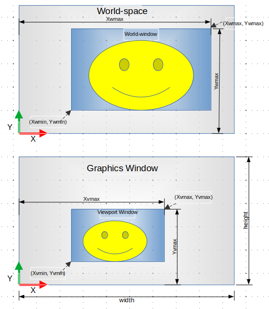
Figure 1: World-to-viewport transform
The window-to-viewport transform matrix can be computed as:
\begin{equation} T_{ W \rightarrow V} = \begin{bmatrix} s_x & 0 & t_x \\ 0 & s_y & t_y \\ 0 & 0 & 1 \\ \end{bmatrix} \end{equation}Where:
\begin{eqnarray*} s_x &=& \frac{\Delta x_{v} }{ \Delta x_{w} } = \frac{ x_{vmax} - x_{vmin} }{x_{wmax} - x_{wmin}} \\ s_y &=& \frac{\Delta y_{v} }{ \Delta y_{w} } = \frac{ y_{vmax} - y_{vmin} }{y_{wmax} - y_{wmin}} \\ t_x &=& x_{vmin} - s_x \cdot x_{wmin} \\ t_y &=& y_{vmin} - s_y \cdot y_{wmin} \\ \end{eqnarray*}Coordinates from world-space can be mapped to the screen-device space by applying the affine transform \(T_{ W \rightarrow V}\) to the world-space coordinates, designated by \(x_w\), \(y_w\).
\begin{equation} \begin{bmatrix} x_v \\ y_v \\ 1 \end{bmatrix} = T_{ W \rightarrow V} \cdot \begin{bmatrix} x_w \\ y_w \\ 1 \end{bmatrix} \end{equation} \begin{equation} \begin{bmatrix} x_v \\ y_v \\ 1 \end{bmatrix} = \begin{bmatrix} s_x \cdot x_w + t_x \\ s_y \cdot y_w + t_y \\ 1 \end{bmatrix} = \begin{bmatrix} s_x (x_w - x_{wmin}) + x_{vmin} \\ s_y (x_y - y_{wmin}) + y_{vmin} \\ 1 \end{bmatrix} \end{equation}Finally, the coordinates \(x_v\) and \(y_v\) can be determined in a more human-friendly way with the following expression:
\begin{eqnarray*} x_v &=& s_x (x_w - x_{wmin}) + x_{vmin} \\ y_v &=& s_y (y_w - y_{wmin}) + y_{vmin} \\ \end{eqnarray*}Image distortion
The world-space propotions will only be preserved when the following predicate holds. For instance, a square in the world-space will look like a rectangle if the rations \(s_x\) and \(s_y\) are not equal.
\begin{equation} s_x = s_y \end{equation}In orther words,
\begin{equation} \frac{ x_{vmax} - x_{vmin} }{x_{wmax} - x_{wmin}} = \frac{ y_{vmax} - y_{vmin} }{y_{wmax} - y_{wmin}} \end{equation}Upper-left coordinate system
If the graphics API has a default upper-left coordinate system, where the origin is at the upper-left corner of the display window and Y axis is pointing downwards. The viewport matrix transform becomes:
\begin{equation} T_{ W \rightarrow VU} = \begin{bmatrix} s_x & 0 & t_x \\ 0 & -s_y & h - t_y \\ 0 & 0 & 1 \\ \end{bmatrix} \end{equation}Then, the \(x_v\), \(y_v\) coordinates can be computed as:
\begin{eqnarray*} x_v &=& +s_x (x_w - x_{wmin}) + x_{vmin} \\ y_v &=& -s_y (y_w - y_{wmin}) + (h - y_{vmin}) \\ \end{eqnarray*}References and further reading:
- Khronos Group - Viewport transform
- "The viewport transform defines the transformation of vertex positions from NDC space to window space. These are the coordinates that are rasterized to the output image. The viewport is defined by a number of viewport parameters. These parameters are set by these functions: glViewport; glDepthRange; glDepthRangef."
- MCA - 301 - Computer Graphics
- Computer Graphics Viewing Objective
- Windows and viewports
- Drawing and coordinate system
1.8.6 3D Affine Transforms
Notations for homogenous coordinate
Point-Vector - for denoting postion, location, point in space or vertex:
- It represents a point or a vertex in space, a coordinate relative to the origin of the coordinate system. Some valid affinte transform operations are translation, rotation, shear and scaling.
Vector - for denoting force, acceleration, or difference between two point-vectors, and so on:
- It represents entities, such as difference between two point-vectors, force, speed, angular speed, acceleration and so on, with a magnitude and direction. It does not make sense to apply translation and scaling to those entities, as a result the pseudo coordinate w is zero for this case.
3D Affine Transforms
3D affine transforms can be represented by matrices with the following format.
\begin{equation} A = \begin{bmatrix} a_{11} & a_{12} & a_{13} & a_{14} \\ a_{21} & a_{22} & a_{23} & a_{24} \\ a_{31} & a_{32} & a_{33} & a_{34} \\ 0 & 0 & 0 & 1 \\ \end{bmatrix} \end{equation}An affine transformation maps the coordinate system (X, Y, Z), which could be an object local coordinate system, to the coordinate system (X', Y', Z'), which could be a world coordinate system. In a similar manner to 2D homogeneous coordinates, an extra pseudo-coordinate w = 1 is added for expressing translations transformations as matrix multiplications, in the same way as rotations.
\begin{equation} \begin{bmatrix} x' \\ y' \\ z' \\ w' = 1 \end{bmatrix} = \begin{bmatrix} a_{11} & a_{12} & a_{13} & a_{14} \\ a_{21} & a_{22} & a_{23} & a_{24} \\ a_{31} & a_{32} & a_{33} & a_{34} \\ 0 & 0 & 0 & 1 \\ \end{bmatrix} \cdot \begin{bmatrix} x \\ y \\ z \\ w = 1 \end{bmatrix} \end{equation} \begin{equation} \begin{bmatrix} x' \\ y' \\ z' \\ 1 \end{bmatrix} = \begin{bmatrix} a_{11} \cdot x + a_{12} \cdot y + a_{13} \cdot z + a_{14} \\ a_{21} \cdot x + a_{22} \cdot y + a_{23} \cdot z + a_{24} \\ a_{31} \cdot x + a_{32} \cdot y + a_{33} \cdot z + a_{34} \\ 1 \end{bmatrix} \end{equation}Combination between affine transforms
Consider two affine transforms \(A = a_{ij}\) and \(B = b_{ij}\). The product between those two transform is also an affine transform.
\begin{equation} C = A \cdot B = \left[\begin{matrix}a_{11} & a_{12} & a_{13} & a_{14}\\a_{21} & a_{22} & a_{23} & a_{24}\\a_{31} & a_{32} & a_{33} & a_{34}\\0 & 0 & 0 & 1\end{matrix}\right] \left[\begin{matrix}b_{11} & b_{12} & b_{13} & b_{14}\\b_{21} & b_{22} & b_{23} & b_{24}\\b_{31} & b_{32} & b_{33} & b_{34}\\0 & 0 & 0 & 1\end{matrix}\right] \end{equation} \begin{equation} C = \left[\begin{matrix}c_{11} & c_{12} & c_{13} & c_{14}\\c_{21} & c_{22} & c_{24} & c_{23}\\c_{31} & c_{32} & c_{33} & c_{34}\\0 & 0 & 0 & 1\end{matrix}\right] \end{equation}Rotation affine transforms
Rotation affine transforms represents rotation around some axis or direction have the following form:
\begin{equation} R = \begin{bmatrix} r_{11} & r_{12} & r_{13} & 0 \\ r_{21} & r_{22} & r_{23} & 0 \\ r_{31} & r_{32} & r_{33} & 0 \\ 0 & 0 & 0 & 1 \\ \end{bmatrix} \end{equation}Properties of Rotation Matrix Affine Transforms:
- Rotation matrices are orthogonal matrices and have the following properties:
- Where:
- R is a rotation matrix
- \(R^T\) is the transpose of the rotation matrix R.
- \(R^{-1}\) is the inverse of the rotation matrix R.
3D Canonical Affine Transforms
Translation:
- Where: \(T^{-1}\) is the inverse transform.
Translation transform applied to an homogeneous vector (x, y, z, w = 1):
\begin{equation} \begin{bmatrix} x' \\ y' \\ z' \\ w' = 1 \end{bmatrix} = \begin{bmatrix} 1 & 0 & 0 & \Delta_x \\ 0 & 1 & 0 & \Delta_y \\ 0 & 0 & 1 & \Delta_z \\ 0 & 0 & 0 & 1 \\ \end{bmatrix} \cdot \begin{bmatrix} x \\ y \\ z \\ w = 1 \end{bmatrix} = \begin{bmatrix} x + \Delta_x \\ y + \Delta_y \\ z + \Delta_z \\ 1 \end{bmatrix} \end{equation}Scaling:
- Where: \(s_x\), \(s_y\), \(s_z\) are the scale factors for axis x, y, z and \(S^{-1}\) is the inverse transform (inverse matrix).
Scaling transform applied to a homogeneous coordinate vector:
\begin{equation} \begin{bmatrix} x' \\ y' \\ z' \\ w' = 1 \end{bmatrix} = S \cdot \begin{bmatrix} x \\ y \\ z \\ w = 1 \end{bmatrix} = \begin{bmatrix} s_x \cdot x \\ s_y \cdot y \\ s_z \cdot z \\ 1 \end{bmatrix} \end{equation}Rotation around x axis
- \(R_x^{-1} = R_x^T\) => The inverse is equal to the transpose.
Transform \(R_x\) applied to a homogeneous vector (X, Y, Z, w = 1).
\begin{equation} \begin{bmatrix} x' \\ y' \\ z' \\ w' = 1 \end{bmatrix} = R_x(\alpha) \cdot \begin{bmatrix} x \\ y \\ z \\ w = 1 \end{bmatrix} = \begin{bmatrix} x \\ y \cdot \cos{\alpha} - z \cdot \sin{\alpha} \\ y \cdot \sin{\alpha} + z \cdot \cos{\alpha} \\ 1 \\ \end{bmatrix} \end{equation}Rotation around y axis
- \(R_y^{-1} = R_y^T\)
Transform \(R_y\) applied to a homogeneous vector:
\begin{equation} \begin{bmatrix} x' \\ y' \\ z' \\ w' = 1 \end{bmatrix} = R_y(\beta) \cdot \begin{bmatrix} x \\ y \\ z \\ w = 1 \end{bmatrix} = \begin{bmatrix} x \cdot \cos{\beta} + z \cdot \sin{\beta} \\ y \\ - x \cdot \sin{\beta} + z \cdot \cos{\beta} \\ \end{bmatrix} \end{equation}Rotation around z axis
- \(R_z^{-1} = R_z^T\)
Transform \(R_z\) applied to a homogeneous vector:
\begin{equation} \begin{bmatrix} x' \\ y' \\ z' \\ w' = 1 \end{bmatrix} = R_z(\theta) \cdot \begin{bmatrix} x \\ y \\ z \\ w = 1 \end{bmatrix} = \begin{bmatrix} x \cdot \cos{\theta} - y \cdot \sin{\theta} \\ x \cdot \sin{\theta} + y \cdot \cos{\theta} \\ z \\ 1 \end{bmatrix} \end{equation}Rotation around arbirtary axis
- Formula 1 : The axis is defined by unit vector \(\hat{n}\)
- References: (Chrobotics), (Ben-Ari - Weizmann) - derived from quaternion equations.
Where:
- \(\hat{n}\) is a unit vector that designates the direction, thus: \(\hat{n} = 1\)
- \(\hat{n} = [x_n \quad y_n \quad z_n]^T\)
- \(x_n\), \(y_n\), \(z_n\) are the components of vector \(\hat{n}\).
- \(a = \cos( \theta / 2)\)
- \(b = x_n \cdot \sin (\theta / 2)\)
- \(c = y_n \cdot \sin (\theta / 2)\)
- \(d = z_n \cdot \sin (\theta / 2)\)
Rotation around arbirtary axis
- Reference: (Steve Rotenberg - Computer Animation)
Where:
- \(\theta\) is the rotation angle around the unit vector \(\hat{n}\)
- \(C = \sin \theta\)
- \(S = \cos \theta\)
- \(\hat{n}\) is a unit vector that designates the direction, thus: \(\hat{n} = 1\)
- \(\hat{n} = [x_n \quad y_n \quad z_n]^T\)
- \(x_n\), \(y_n\), \(z_n\) are the components of vector \(\hat{n}\).
Testing formula in Sympy - Python CAS (Computer Algebra System):
import sympy

# t represents the angle theta
x, y, z, t = symbols('x y z t')
C, S = symbols("C S")

row1 = [ x**2 + C * (1 - x**2), x * y * (1 - C) - z * S, x * z * (1 - C)  + y * S ]
row2 = [ x * y * (1 - C) + z * S, y**2 + C * (1 - y**2), y * z * (1 - C) - x * S ]
row3 = [ x * z * (1 - C) - y * S,  y * z * (1 - C) +  x * S, z**2 + C * (1 - z**2) ]

m = Matrix([row1, row2, row3])

# C = cos(t)
# S = sin(t)

In [7]: m
Out[7]:
⎡   ⎛     2⎞    2                                          ⎤
⎢ C⋅⎝1 - x ⎠ + x     -S⋅z + x⋅y⋅(1 - C)  S⋅y + x⋅z⋅(1 - C) ⎥
⎢                                                          ⎥
⎢                       ⎛     2⎞    2                      ⎥
⎢S⋅z + x⋅y⋅(1 - C)    C⋅⎝1 - y ⎠ + y     -S⋅x + y⋅z⋅(1 - C)⎥
⎢                                                          ⎥
⎢                                           ⎛     2⎞    2  ⎥
⎣-S⋅y + x⋅z⋅(1 - C)  S⋅x + y⋅z⋅(1 - C)    C⋅⎝1 - z ⎠ + z   ⎦

# --- Determine rotation matrix around Z axis (Particular case) ------#
#

In [8]: m.subs({x: 0, y: 0, z: 1})
Out[8]:
⎡C  -S  0⎤
⎢        ⎥
⎢S  C   0⎥
⎢        ⎥
⎣0  0   1⎦

In [11]: rotZ = m.subs({x: 0, y: 0, z: 1, C: cos(t), S: sin(t) })

In [12]: rotZ
Out[12]:
⎡cos(t)  -sin(t)  0⎤
⎢                  ⎥
⎢sin(t)  cos(t)   0⎥
⎢                  ⎥
⎣  0        0     1⎦


#---- Determine rotation matrix around X axis (Particular case) ------#
#
In [14]: rotX = m.subs({x: 1, y: 0, z: 0, C: cos(t), S: sin(t) })

In [15]: rotX
Out[15]:
⎡1    0        0   ⎤
⎢                  ⎥
⎢0  cos(t)  -sin(t)⎥
⎢                  ⎥
⎣0  sin(t)  cos(t) ⎦

#---- Determine rotation matrix around Y axis (Particular case) ------#
#
In [16]: rotY = m.subs({x: 0, y: 1, z: 0, C: cos(t), S: sin(t) })

In [17]: rotY
Out[17]:
⎡cos(t)   0  sin(t)⎤
⎢                  ⎥
⎢   0     1    0   ⎥
⎢                  ⎥
⎣-sin(t)  0  cos(t)⎦
1.8.7 Rotation Matrix and Rodrigues' Rotation Formula
The Rodrigues' Rotation formula, named after the mathematician Olinde Rodrigues, allows rotating a vector in a 3D space, given an axis unit vector and a rotation angle around this axis. Variants of this formula can be used for determining the rotation matrix around any axis and for computing the axis-angle equivalent of a rotation matrix. This formula has wide variety of applications, including computer graphics, games, robotics, mechanical engineering and aerospace design.
Consider the following picture that contains a vector \('\boldsymbol{v}\) which is the position vector \(\boldsymbol{v}\) rotated by an angle \(\theta\) around an axis designated by the unite vector \(\boldsymbol{n}\). The vector \(\boldsymbol{v}_p\) is the projection of vector \(\boldsymbol{v}\) onto the vector \(\boldsymbol{n}\) and the vector \(\boldsymbol{v}_r\) is the rejection of vector \(\boldsymbol{v}\).
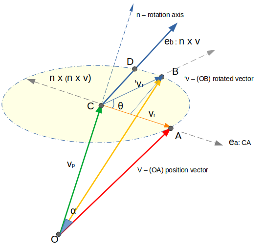
Figure 2: Rotation of position vector around an axis
According to the previous picture it is possible to find the following expressions. Where r is the radius of the circle, which is the same as the lenght of CA.
\(\boldsymbol{v}_p\) and \(\boldsymbol{v}_r\) that
\begin{equation} \| \boldsymbol{v}_p \| = \| v \| \cos \alpha \end{equation} \begin{equation} r = \| \boldsymbol{v}_r \| = \| v \| \sin \alpha \end{equation}The projection vector \(\boldsymbol{v_p}\) (OC) can be determined using the following identity:
\begin{equation} v_p = (\boldsymbol{n} \cdot \boldsymbol{v}) \boldsymbol{n} \end{equation}The cross product between vectors \(\boldsymbol{n}\) and vector \(\boldsymbol{v}\) is computed as:
\begin{equation} \| \boldsymbol{n} \times \boldsymbol{v} \| = \| \boldsymbol{n} \| \| \boldsymbol{v} \| \sin \alpha = \| \boldsymbol{v} \| \sin \alpha \end{equation}Knowing that \(\| \boldsymbol{v}_r = \| \boldsymbol{v} \| \sin \alpha\), the following can be determined:
\begin{equation} r = \| \boldsymbol{v}_r \| = \| \boldsymbol{n} \times \boldsymbol{v} \| = \| \boldsymbol{v} \| \sin \alpha \end{equation}The vector \(\boldsymbol{n} \times (\boldsymbol{n} \times \boldsymbol{v})\) is orthogonal to both \(\boldsymbol{n}\) and \(\boldsymbol{n} \times \boldsymbol{v}\) and has opposite direction to the vector \(\boldsymbol{v_r}\). The norm/magnitude of this cross product vector is determined by using the cross product identity.
\begin{equation} \| \boldsymbol{n} \times (\boldsymbol{n} \times \boldsymbol{v} ) \| = \| \boldsymbol{n} \| \| \boldsymbol{n} \times \boldsymbol{v} \| = \| \boldsymbol{n} \times \boldsymbol{v} \| = \| \boldsymbol{v}_r \| \end{equation}Since the vector \(\boldsymbol{n} \times (\boldsymbol{n} \times \boldsymbol{v})\) has the same magnitude as the vector \(\boldsymbol{v}_r\) and opposite direction, it is possible to find that.
\begin{equation} \boldsymbol{v}_r = - \boldsymbol{n} \times (\boldsymbol{n} \times \boldsymbol{v}) \end{equation}The projection vector \(\boldsymbol{v}_p\) can also be computed in terms of rejection vector \(\boldsymbol{v}_r\) by using the expression \(\boldsymbol{v} = \boldsymbol{v}_p + \boldsymbol{v}_r\).
\begin{equation} \boldsymbol{v}_p = \boldsymbol{v} - \boldsymbol{v}_r = \boldsymbol{v} - (- \boldsymbol{n} \times (\boldsymbol{n} \times \boldsymbol{v}) ) \end{equation} \begin{equation} \boldsymbol{v}_p = \boldsymbol{v} + \boldsymbol{n} \times (\boldsymbol{n} \times \boldsymbol{v}) \end{equation}The unit vector \(\boldsymbol{e}_a\) that has the same direction as the vector \(\boldsymbol{v}_r\) and it can computed as:
\begin{equation} \boldsymbol{e}_a = - \frac{1}{ \| \boldsymbol{n} \times (\boldsymbol{n} \times \boldsymbol{v}) \| } \boldsymbol{n} \times (\boldsymbol{n} \times \boldsymbol{v}) = - \frac{1}{ \| \boldsymbol{n} \times \boldsymbol{v} \| } \boldsymbol{n} \times (\boldsymbol{n} \times \boldsymbol{v}) \end{equation}The unit vector \(\boldsymbol{e}_b\) (direction CD), the same direction of vector \(\boldsymbol{n} \times \boldsymbol{v}\) is orthogonal to \(\boldsymbol{n}\), \(\boldsymbol{v}\) and \(\boldsymbol{v}_r\) is determined by normalizing the vector \(\boldsymbol{n} \times \boldsymbol{v}\).
\begin{equation} \boldsymbol{e}_b = \frac{ \boldsymbol{n} \times \boldsymbol{v} } {\| \boldsymbol{n} \times \boldsymbol{v} \|} \end{equation}By projecting the rotated rejection vector \('\boldsymbol{v}_r\) on the vectors \(\boldsymbol{e}_a\) and \(\boldsymbol{e}_b\), the next expression is found as follow:
\begin{equation} \boldsymbol{v}_r' = r \cos(\theta) \boldsymbol{e}_a + r \sin(\theta) \boldsymbol{e}_b \end{equation} \begin{equation} \boldsymbol{v}_r' = \| \boldsymbol{n} \times \boldsymbol{v} \| \cos(\theta) ( - \frac{1}{ \| \boldsymbol{n} \times \boldsymbol{v} \| } \boldsymbol{n} \times (\boldsymbol{n} \times \boldsymbol{v}) ) + \| \boldsymbol{n} \times \boldsymbol{v} \| \sin(\theta) \frac{ \boldsymbol{n} \times \boldsymbol{v} } {\| \boldsymbol{n} \times \boldsymbol{v} \|} \end{equation} \begin{equation} \boldsymbol{v}_r' = - \cos(\theta) \boldsymbol{n} \times (\boldsymbol{n} \times \boldsymbol{v}) + \sin(\theta) \boldsymbol{n} \times \boldsymbol{v} \end{equation}The rotated vector \(\boldsymbol{v}'\) can be found by adding the rotated rejection vector \(\boldsymbol{v}_r'\) and the projection vector \(\boldsymbol{v}_p\), replacing the vector \(\boldsymbol{v}_p\) with \(\boldsymbol{v} + \boldsymbol{n} \times (\boldsymbol{n} \times \boldsymbol{v})\) and also replacing the \(\boldsymbol{e}_a\) and \(\boldsymbol{e}_b\) with its previous values.
\begin{equation} \boldsymbol{v}' = \boldsymbol{v}_p + \boldsymbol{v}_r' = (\boldsymbol{v} + \boldsymbol{n} \times (\boldsymbol{n} \times \boldsymbol{v}) ) + ( - \cos(\theta) \boldsymbol{n} \times (\boldsymbol{n} \times \boldsymbol{v}) + \sin(\theta) \boldsymbol{n} \times \boldsymbol{v} ) \end{equation} \begin{equation} \boldsymbol{v}' = \boldsymbol{v} + \boldsymbol{n} \times (\boldsymbol{n} \times \boldsymbol{v}) - \cos(\theta) \boldsymbol{n} \times (\boldsymbol{n} \times \boldsymbol{v}) + \sin(\theta) \boldsymbol{n} \times \boldsymbol{v} \end{equation}Finally, by further simplyfing the previous expression, it possible to find the Rodriguez's formula for rotation:
\begin{equation} \boxed{ \boldsymbol{v}' = \boldsymbol{v} + (1 - \cos \theta )\boldsymbol{n} \times (\boldsymbol{n} \times \boldsymbol{v}) + ( \sin \theta ) \boldsymbol{n} \times \boldsymbol{v} } \end{equation}The cross product can be written as a matrix multiplication by using the cross product matrix \([\boldsymbol{u}]_{\times}\) operator defined as:
\begin{equation} [\boldsymbol{u}]_{\times} = \begin{pmatrix} 0 & -u_z & u_y \\ u_z & 0 & -u_x \\ -u_y & u_x & 0 \\ \end{pmatrix} \end{equation}Cross-product represented as matrix multiplication.
\begin{equation} \boldsymbol{n} \times \boldsymbol{v} = [ \boldsymbol{n} ]_{\times} \boldsymbol{v} \end{equation}The Rodriguez's formula for rotation can be formulated as a matrix multiplication by replacing cross-product operations with matrix multiplication where \(\boldsymbol{I}\) is a 3 x 3 identity matrix.
\begin{equation} \boldsymbol{v}' = \boldsymbol{v} + (1 - \cos \theta ) [ \boldsymbol{n}]_{\times} ( [\boldsymbol{n}]_{\times} \boldsymbol{v}) + ( \sin \theta ) [ \boldsymbol{n}]_{\times} \boldsymbol{v} \end{equation} \begin{equation} \boldsymbol{v}' = \boldsymbol{I} \boldsymbol{v} + (1 - \cos \theta ) [\boldsymbol{n}]_{\times}^2 \boldsymbol{v} + ( \sin \theta ) [\boldsymbol{n}]_{\times} \boldsymbol{v} \end{equation} \begin{equation} \boldsymbol{v}' = \left( \boldsymbol{I} + (1 - \cos \theta ) [\boldsymbol{n}]_{\times}^2 + ( \sin \theta ) [\boldsymbol{n}]_{\times} \right) \boldsymbol{v} \end{equation}So, the rotation matrix R such that \(\boldsymbol{v}' = R \boldsymbol{v}\) can be found as the following expression, where \(N = [\boldsymbol{n}]_{\times}\) is the cross product matrix of the rotation axis vector and \(\boldsymbol{I}\) is a 3 x 3 identity matrix. In computer graphics, it is more efficient to compute the rotation matrix only once and use to rotate all vertices of an object on the GPU side instead of applying the Rodriguez's formula to every object vertex.
\begin{equation} R = \boldsymbol{I} + (\sin \theta) [\boldsymbol{n}]_{\times} + (1 - \cos \theta ) [\boldsymbol{n}]_{\times}^2 \end{equation} \begin{equation} \boxed{ R = \boldsymbol{I} + (\sin \theta) N + (1 - \cos \theta ) N^2 } \end{equation}Deriving the Rotation Matrix in Wolfram Mathemtica
The general rotation matrix R can be easily found by using a CAS - Computer Algebra System such as Wolfram Mathematica, SymPy (Python) library or GNU Maxima. In this case, it is used Wolfram Mathematica for determining this matrix due to its ease of use and its rule-rewriting systems that makes it easier to manipulate math formulas and generate LaTex, Mathml, ascii representation, C, C++ or Fortran code. An alternative CAS is mathics, a free and open source alternative implementation of Wolfram programming language, built on top of Python's sympy library for symbolic math computation.
Run Mathics => Mathematica Computer Algebra System clone for Python:
Run interactive shell on command line:
docker run --rm -it --security-opt=seccomp=unconfined \
        --name=mathics-cli --volume=/tmp:/usr/src/app/data \
        mathicsorg/mathics --mode cli

Mathicscript: 6.0.0, Mathics 6.0.0
on CPython 3.10.6 (main, Nov 14 2022, 16:10:14) [GCC 11.3.0]

Using:
SymPy 1.9, mpmath 1.2.1, numpy 1.21.5
cython Not installed, matplotlib 3.5.1,
Asymptote version 2.83

Copyright (C) 2011-2023 The Mathics Team.
This program comes with ABSOLUTELY NO WARRANTY.
This is free software, and you are welcome to redistribute it
under certain conditions.
See the documentation for the full license.

Quit by evaluating Quit[] or by pressing CONTROL-D.

In[1]:=
Run graphics notebook - web interface on port 9080 using docker. After the container initialization, open the URL http://localhost:9080 on the Web browser.
$  docker run --rm -it --security-opt=seccomp=unconfined --name=mathics-cli -p=9080:8000 \
     --volume=/tmp:/usr/src/app/data mathicsorg/mathics  --mode ui
Wolfram Mathematica or Mathics session:
(* Define the rotation axis *)
n = {nx, ny, nz}

(* Turns a vector in to its cross product matrix *)
cross[u_] := {{0, -u[[3]], u[[2]] }, { u[[3]], 0, -u[[1]]}, {-u[[2]], u[[1]], 0} }


In[6]:= I3 = IdentityMatrix[3]

Out[6]= {{1, 0, 0}, {0, 1, 0}, {0, 0, 1}}

In[7]:= I3 // MatrixForm

Out[7]//MatrixForm= 1   0   0

                    0   1   0

                    0   0   1

 In[8]:= xN = cross[n] (* Cross product matrix of rotation axis n*)

 Out[8]= {{0, -nz, ny}, {nz, 0, -nx}, {-ny, nx, 0}}

 In[9]:= xN // MatrixForm

 Out[9]//MatrixForm= 0     -nz   ny

                     nz    0     -nx

                     -ny   nx    0


 In[10]:= R = I3 + S * xN + (1 - C) * (xN . xN)

                            2     2
 Out[10]= {{1 + (1 - C) (-ny  - nz ), (1 - C) nx ny - nz S,

                                                                     2     2
 >     (1 - C) nx nz + ny S}, {(1 - C) nx ny + nz S, 1 + (1 - C) (-nx  - nz ),

 >     (1 - C) ny nz - nx S}, {(1 - C) nx nz - ny S, (1 - C) ny nz + nx S,

                       2     2
 >     1 + (1 - C) (-nx  - ny )}}

 In[11]:=
 In[11]:= R = I3 + S * xN + (1 - C) * MatrixPower[xN, 2] (* Note: a^2 - does not work with matrices *)

                            2     2
 Out[11]= {{1 + (1 - C) (-ny  - nz ), (1 - C) nx ny - nz S,

                                                                     2     2
 >     (1 - C) nx nz + ny S}, {(1 - C) nx ny + nz S, 1 + (1 - C) (-nx  - nz ),

 >     (1 - C) ny nz - nx S}, {(1 - C) nx nz - ny S, (1 - C) ny nz + nx S,

                       2     2
 >     1 + (1 - C) (-nx  - ny )}}


 rotX = { nx -> 1, ny -> 0, nz -> 0,  C -> Cos[ \[Theta] ], S -> Sin[ \[Theta] ] };
 rotY = { nx -> 0, ny -> 1, nz -> 0,  C -> Cos[ \[Theta] ], S -> Sin[ \[Theta] ] };
 rotZ = { nx -> 0, ny -> 0, nz -> 1,  C -> Cos[ \[Theta] ], S -> Sin[ \[Theta] ] };


 (* --------------- Rotation Matrix around X axis  -------------------------------*)

 In[26]:= Rx = R /. rotX

 Out[26]= {{1, 0, 0}, {0, Cos[θ], -Sin[θ]}, {0, Sin[θ], Cos[θ]}}

 In[27]:= Rx // MatrixForm

 Out[27]//MatrixForm= 1          0          0

                      0          Cos[θ]    -Sin[θ]

                      0          Sin[θ]    Cos[θ]

 In[28]:= Rx // MatrixForm // TeXForm

 Out[28]//TeXForm= \left(
                   \begin{array}{ccc}
                    1 & 0 & 0 \\
                    0 & \cos (\theta ) & -\sin (\theta ) \\
                    0 & \sin (\theta ) & \cos (\theta ) \\
                   \end{array}
                   \right)

 (* --------------- Rotation Matrix around Y axis  -------------------------------*)

 In[31]:= Ry = R /. rotY

 Out[31]= {{Cos[θ], 0, Sin[θ]}, {0, 1, 0}, {-Sin[θ], 0, Cos[θ]}}

 In[32]:= Ry // MatrixForm

 Out[32]//MatrixForm= Cos[θ]    0          Sin[θ]

                      0          1          0

                      -Sin[θ]   0          Cos[θ]

 In[33]:= Ry // MatrixForm // TeXForm

 Out[33]//TeXForm= \left(
                   \begin{array}{ccc}
                    \cos (\theta ) & 0 & \sin (\theta ) \\
                    0 & 1 & 0 \\
                    -\sin (\theta ) & 0 & \cos (\theta ) \\
                   \end{array}
                   \right)

 (* --------------- Rotation Matrix around Z axis  -------------------------------*)

 In[34]:= Rz = R /. rotZ

 Out[34]= {{Cos[θ], -Sin[θ], 0}, {Sin[θ], Cos[θ], 0}, {0, 0, 1}}

 In[35]:= Rz // MatrixForm

 Out[35]//MatrixForm= Cos[θ]    -Sin[θ]   0

                      Sin[θ]    Cos[θ]    0

                      0          0          1

 In[36]:= Rz // MatrixForm // TeXForm

 Out[36]//TeXForm= \left(
                   \begin{array}{ccc}
                    \cos (\theta ) & -\sin (\theta ) & 0 \\
                    \sin (\theta ) & \cos (\theta ) & 0 \\
                    0 & 0 & 1 \\
                   \end{array}
                   \right)

 (* -------------- General Rotation Matrix --------------------------------------- *)

In[41]:= Clear[n]
In[42]:= Rp = R /. { nx -> Subscript[n, x], ny -> Subscript[n, y], nz -> Subscript[n, z] };

In[44]:= Rp // MatrixForm // TeXForm

Out[44]//TeXForm=
  \left(
  \begin{array}{ccc}
   (1-C) \left(-n_y^2-n_z^2\right)+1 & (1-C) n_x n_y-S n_z & (1-C) n_x n_z+S
     n_y \\
   (1-C) n_x n_y+S n_z & (1-C) \left(-n_x^2-n_z^2\right)+1 & (1-C) n_y n_z-S
     n_x \\
   (1-C) n_x n_z-S n_y & (1-C) n_y n_z+S n_x & (1-C)
     \left(-n_x^2-n_y^2\right)+1 \\
  \end{array}
  \right)


 In[52]:= R2 = R /. {-ny^2 - nz^2 -> nx^2 - 1, -nx^2 - nz^2 -> ny^2 - 1, -nx^2 - ny^2 -> nz^2 - 1 }

                                2
 Out[52]= {{1 + (1 - C) (-1 + nx ), (1 - C) nx ny - nz S,

                                                                         2
 >     (1 - C) nx nz + ny S}, {(1 - C) nx ny + nz S, 1 + (1 - C) (-1 + ny ),

 >     (1 - C) ny nz - nx S}, {(1 - C) nx nz - ny S, (1 - C) ny nz + nx S,

                           2
 >     1 + (1 - C) (-1 + nz )}}


 In[53]:= Rp2 = R2 /. { nx -> Subscript[n, x], ny -> Subscript[n, y], nz -> Subscript[n, z] };

 In[54]:= Rp2

                                2
 Out[54]= {{1 + (1 - C) (-1 + n  ), (1 - C) n  n  - S n ,
                               x             x  y      z

                                                                         2
 >     S n  + (1 - C) n  n }, {(1 - C) n  n  + S n , 1 + (1 - C) (-1 + n  ),
          y            x  z             x  y      z                     y

 >     -(S n ) + (1 - C) n  n },
            x             y  z

                                                                          2
 >    {-(S n ) + (1 - C) n  n , S n  + (1 - C) n  n , 1 + (1 - C) (-1 + n  )}}
            y             x  z     x            y  z                     z


 In[55]:= Rp2 // MatrixForm // TeXForm

 Out[55]//TeXForm=
    \left(
    \begin{array}{ccc}
     (1-C) \left(n_x^2-1\right)+1 & (1-C) n_x n_y-S n_z & (1-C) n_x n_z+S n_y
       \\
     (1-C) n_x n_y+S n_z & (1-C) \left(n_y^2-1\right)+1 & (1-C) n_y n_z-S n_x
       \\
     (1-C) n_x n_z-S n_y & (1-C) n_y n_z+S n_x & (1-C) \left(n_z^2-1\right)+1
       \\
    \end{array}
    \right)
The overall rotation matrix around an arbitrary axis is given by the following expression where \(n_x\), \(n_y\) and \(n_z\) are components of the rotation axis vector \(\boldsymbol{n}\) (unitary vector); \(\theta\) is the rotation angle; \(C = \sin \theta\); and \(S = \sin \theta\).
\begin{equation} R = \begin{bmatrix} (1-C) \left(-n_y^2-n_z^2\right)+1 & (1-C) n_x n_y-S n_z & (1-C) n_x n_z+S n_y \\ (1-C) n_x n_y+S n_z & (1-C) \left(-n_x^2-n_z^2\right)+1 & (1-C) n_y n_z-S n_x \\ (1-C) n_x n_z-S n_y & (1-C) n_y n_z+S n_x & (1-C) \left(-n_x^2-n_y^2\right)+1 \\ \end{bmatrix} \end{equation}The general rotation matrix can also be expressed in this form that is obtained by replacing \(n_x^2 - 1 = - (n_y^2 + nz^2)\), \(n_y^2 - 1 = - (n_x^2 + nz^2)\) and \(n_z^2 - 1 = - (n_x^2 + ny^2)\).
\begin{equation} \boxed{ R = \begin{bmatrix} (1-C) \left(n_x^2-1\right)+1 & (1-C) n_x n_y-S n_z & (1-C) n_x n_z+S n_y \\ (1-C) n_x n_y+S n_z & (1-C) \left(n_y^2-1\right)+1 & (1-C) n_y n_z-S n_x \\ (1-C) n_x n_z-S n_y & (1-C) n_y n_z+S n_x & (1-C) \left(n_z^2-1\right)+1 \\ \end{bmatrix} } \end{equation}Rotation matrix around X axis.
\begin{equation} \boxed{ R_x = \left( \begin{array}{ccc} 1 & 0 & 0 \\ 0 & \cos (\theta ) & -\sin (\theta ) \\ 0 & \sin (\theta ) & \cos (\theta ) \\ \end{array} \right) } \end{equation}Rotation matrix around Y axis.
\begin{equation} \boxed{ R_y = \left( \begin{array}{ccc} \cos (\theta ) & 0 & \sin (\theta ) \\ 0 & 1 & 0 \\ -\sin (\theta ) & 0 & \cos (\theta ) \\ \end{array} \right) } \end{equation}Rotation matrix around Z axis.
\begin{equation} \boxed{ R_z = \left( \begin{array}{ccc} \cos (\theta ) & -\sin (\theta ) & 0 \\ \sin (\theta ) & \cos (\theta ) & 0 \\ 0 & 0 & 1 \\ \end{array} \right) } \end{equation}Rodriguez Formula in Alternative Format
From previous equation, the unit vector \(\boldsymbol{e}_a\) can be found as:
\begin{equation} \boldsymbol{e}_a = \frac{ \boldsymbol{v}_r }{ \| \boldsymbol{v}_r \| } = \frac{\boldsymbol{v} - (\boldsymbol{v} \cdot \boldsymbol{n}) \boldsymbol{n}} { \| \boldsymbol{n} \times \boldsymbol{v} \| } \end{equation} \begin{equation} \boldsymbol{v}_r' = r \cos(\theta) \boldsymbol{e}_a + r \sin(\theta) \boldsymbol{e}_b \end{equation} \begin{equation} \boldsymbol{v}_r' = \| \boldsymbol{n} \times \boldsymbol{v} \| \cos(\theta) ( \frac{\boldsymbol{v} - (\boldsymbol{v} \cdot \boldsymbol{n}) \boldsymbol{n}} { \| \boldsymbol{n} \times \boldsymbol{v} \| } ) + \| \boldsymbol{n} \times \boldsymbol{v} \| \sin(\theta) \frac{ \boldsymbol{n} \times \boldsymbol{v} } {\| \boldsymbol{n} \times \boldsymbol{v} \|} \end{equation} \begin{equation} \boldsymbol{v}_r' = \cos(\theta) ( \boldsymbol{v} - (\boldsymbol{v} \cdot \boldsymbol{n}) \boldsymbol{n} ) + \sin(\theta) \boldsymbol{n} \times \boldsymbol{v} \end{equation}Then, rotated vector \(\boldsymbol{v}'\) can be found by replacing the values of previous equations in the next equation.
\begin{equation} \boldsymbol{v}' = \boldsymbol{v}_p + \boldsymbol{v}_r' \end{equation} \begin{equation} \boldsymbol{v}' = (\boldsymbol{v} \cdot \boldsymbol{n}) \boldsymbol{n} + ( \cos(\theta) ( \boldsymbol{v} - (\boldsymbol{v} \cdot \boldsymbol{n}) \boldsymbol{n} ) + \sin(\theta) \boldsymbol{n} \times \boldsymbol{v} ) \end{equation}Alternative Format of Roriguez Formula: Finally, the alternative format of Rodriguez Formula for rotation can be determined as follow.
\begin{equation} \boldsymbol{v}' = \boldsymbol{v} \cos \theta + (1 - \cos \theta) (\boldsymbol{v} \cdot \boldsymbol{n}) \boldsymbol{n} + (\boldsymbol{n} \times \boldsymbol{v}) \sin \theta \end{equation}It can be found that the previous expression can be turned into a matrix multiplication as in shown in the next equation where \(a^T\) is the tranpose of matrix a; I 3x3 identiy matrix; \(N = [\boldsymbol{b}]_{\times}\) is the cross product matrix of rotation axis vector \(\boldsymbol{n}\). In this case, the vectors \(\boldsymbol{v}\), \(\boldsymbol{v}'\) and \(\boldsymbol{n}\) are treated as 3 x 1 (3 by 1) column matrices.
\begin{equation} \boldsymbol{v}' = I \boldsymbol{v} \cos \theta + (1 - \cos \theta)(\boldsymbol{n} \boldsymbol{n}^T) \boldsymbol{v} + (N \sin \theta) \boldsymbol{v} \end{equation} \begin{equation} \boldsymbol{v}' = I \boldsymbol{v} \cos \theta + (1 - \cos \theta)(\boldsymbol{n} \boldsymbol{n}^T) \boldsymbol{v} + (N \sin \theta) \boldsymbol{v} \end{equation} \begin{equation} \boldsymbol{v}' = \left( I \cos \theta + (1 - \cos \theta)\boldsymbol{n} \boldsymbol{n}^T + N \sin(\theta) \right) \boldsymbol{v} \end{equation} \begin{equation} \boldsymbol{v}' = \left( \boldsymbol{n} \boldsymbol{n}^T + (I - \boldsymbol{n} \boldsymbol{n}^T ) \cos \theta + N \sin(\theta) \right) \boldsymbol{v} \end{equation}So, the general rotation matrix R that represents a rotation around an arbitrary axis such that \(\boldsymbol{v}' = R \boldsymbol{v}\) can be found as:
\begin{equation} R = \boldsymbol{n} \boldsymbol{n}^T + (I - \boldsymbol{n} \boldsymbol{n}^T ) \cos \theta + N \sin \theta \end{equation}The rotation matrix can be determined from this expression by using Wolfram Mathematica computer algebra system.
In[1]:= n = { {nx}, {ny}, {nz} }

Out[1]= {{nx}, {ny}, {nz}}

In[2]:= Dimensions[n]

Out[2]= {3, 1}

In[3]:= n // MatrixForm

Out[3]//MatrixForm= nx

                    ny

                    nz

In[4]:= P = n . Transpose[n]

            2                           2                           2
Out[4]= {{nx , nx ny, nx nz}, {nx ny, ny , ny nz}, {nx nz, ny nz, nz }}

In[5]:= P // MatrixForm

Out[5]//MatrixForm=   2
                    nx      nx ny   nx nz

                              2
                    nx ny   ny      ny nz

                                      2
                    nx nz   ny nz   nz


In[6]:= I3 = IdentityMatrix[3]

Out[6]= {{1, 0, 0}, {0, 1, 0}, {0, 0, 1}}

In[7]:= SN = {{0, -nz, ny}, {nz, 0, -nx}, {-ny, nx, 0}};

(* C - represents cos(t), S - represents sin(t) *)
In[8]:= R = P + (I3 - P) * C + SN * S


In[9]:= R // MatrixForm

Out[9]//MatrixForm=

>     2            2
    nx  + C (1 - nx )        nx ny - C nx ny - nz S   nx nz - C nx nz + ny S

                               2            2
    nx ny - C nx ny + nz S   ny  + C (1 - ny )        ny nz - C ny nz - nx S

                                                        2            2
    nx nz - C nx nz - ny S   ny nz - C ny nz + nx S   nz  + C (1 - nz )


rotX = { nx -> 1, ny -> 0, nz -> 0,  C -> Cos[ \[Theta] ], S -> Sin[ \[Theta] ] };
rotY = { nx -> 0, ny -> 1, nz -> 0,  C -> Cos[ \[Theta] ], S -> Sin[ \[Theta] ] };
rotZ = { nx -> 0, ny -> 0, nz -> 1,  C -> Cos[ \[Theta] ], S -> Sin[ \[Theta] ] };


In[14]:= Rx = R /. rotX

Out[14]= {{1, 0, 0}, {0, Cos[θ], -Sin[θ]}, {0, Sin[θ], Cos[θ]}}


In[15]:= Rx // MatrixForm

Out[15]//MatrixForm= 1          0          0

                     0          Cos[θ]    -Sin[θ]

                     0          Sin[θ]    Cos[θ]


In[16]:= Ry = R /. rotY

Out[16]= {{Cos[θ], 0, Sin[θ]}, {0, 1, 0}, {-Sin[θ], 0, Cos[θ]}}

In[17]:= MatrixForm[Ry]

Out[17]//MatrixForm= Cos[θ]    0          Sin[θ]

                     0          1          0

                     -Sin[θ]   0          Cos[θ]


In[18]:= Rz = R /. rotZ

Out[18]= {{Cos[θ], -Sin[θ], 0}, {Sin[θ], Cos[θ], 0}, {0, 0, 1}}

In[19]:= Rz // MatrixForm

Out[19]//MatrixForm= Cos[θ]    -Sin[θ]   0

                     Sin[θ]    Cos[θ]    0

                     0          0          1


In[27]:= ClearAll[n]

In[28]:= toSubscr =  { nx -> Subscript[n, x], ny -> Subscript[n, y], nz -> Subscript[n, z]};

In[29]:= Rp = R /. toSubscr;


In[31]:= Rp

             2            2
Out[31]= {{n   + C (1 - n  ), n  n  - C n  n  - S n ,
            x            x     x  y      x  y      z

                                                          2            2
>     S n  + n  n  - C n  n }, {n  n  - C n  n  + S n , n   + C (1 - n  ),
         y    x  z      x  z     x  y      x  y      z   y            y

>     -(S n ) + n  n  - C n  n },
           x     y  z      y  z

                                                           2            2
>    {-(S n ) + n  n  - C n  n , S n  + n  n  - C n  n , n   + C (1 - n  )}}
           y     x  z      x  z     x    y  z      y  z   z            z


In[33]:= Rp // MatrixForm // TeXForm

Out[33]//TeXForm=
   \left(
   \begin{array}{ccc}
    C \left(1-n_x^2\right)+n_x^2 & -C n_x n_y-S n_z+n_x n_y & -C n_x n_z+S
      n_y+n_x n_z \\
    -C n_x n_y+S n_z+n_x n_y & C \left(1-n_y^2\right)+n_y^2 & -C n_y n_z-S
      n_x+n_y n_z \\
    -C n_x n_z-S n_y+n_x n_z & -C n_y n_z+S n_x+n_y n_z & C
      \left(1-n_z^2\right)+n_z^2 \\
   \end{array}
   \right)
Finally, from Wolfram mathematica session, the rotation matrix can be determined as:
\begin{equation} \boxed{ R = \begin{bmatrix} C \left(1-n_x^2\right)+n_x^2 & -C n_x n_y-S n_z+n_x n_y & -C n_x n_z+S n_y+n_x n_z \\ -C n_x n_y+S n_z+n_x n_y & C \left(1-n_y^2\right)+n_y^2 & -C n_y n_z-S n_x+n_y n_z \\ -C n_x n_z-S n_y+n_x n_z & -C n_y n_z+S n_x+n_y n_z & C \left(1-n_z^2\right)+n_z^2 \\ \end{bmatrix} } \end{equation}Computing the General Rotation Matrix using Sympy
Install Python Sympy library:
$ pip3 install --user sympy
Sympy import:
from sympy import *
init_printing('utf-8')
Define symbolic variables:
nx, ny, nz, q, C, S = symbols("nx ny nz theta C S")
Define function that turns vector into cross-product matrix.
def crossm(v):
    "Generate cross-product matrix"
    x = v[0]
    y = v[1]
    z = v[2]
    m = Matrix([[0, -z, y], [z, 0, -x], [-y, x, 0]])
    return m
Identity matrix.
>>> I3 = Matrix([[1, 0, 0], [0, 1, 0], [0, 0, 1]])

>>> I3
⎡1  0  0⎤
⎢       ⎥
⎢0  1  0⎥
⎢       ⎥
⎣0  0  1⎦
Define rotation axis unit vector \(\mathbf{n}\)
>>> n = Matrix([nx, ny, nz])

>>> n
⎡nx⎤
⎢  ⎥
⎢ny⎥
⎢  ⎥
⎣nz⎦
Cross-product matrix \([\mathbf{n}]_{\times}\), equivalent to the the cross product operator \([\mathbf{u}_{\times}] \mathbf{v} = \mathbf{u} \times \mathbf{v}\).
>>> xN = crossm(n)

>>> xN
⎡ 0   -nz  ny ⎤
⎢             ⎥
⎢nz    0   -nx⎥
⎢             ⎥
⎣-ny  nx    0 ⎦
Check the cross-product matrix is correctness \(\mathbf{n} \times \mathbf{n} = [\mathbf{n}]_{\times} \mathbf{n} = \mathbf{0}\). The product of the cross-product matrix of a vector by itself should be a zero vector. Note: The matrix multiplication operator of Sympy is (*), not (@) 'at' like Python's numpy.
>>> xN * n
⎡0⎤
⎢ ⎥
⎢0⎥
⎢ ⎥
⎣0⎦
Compute the general rotation matrix.
\begin{equation*} R = \boldsymbol{n} \boldsymbol{n}^T + (I - \boldsymbol{n} \boldsymbol{n}^T ) \cos \theta + [\mathbf{n}]_{\times} \sin \theta \end{equation*}>>> R = n * n.T + (I3 - n * n.T) * C + xN * S
>>> R
⎡ ⎛ 2⎞ 2 ⎤
⎢ C⋅⎝1 - nx ⎠ + nx -C⋅nx⋅ny - S⋅nz + nx⋅ny -C⋅nx⋅nz + S⋅ny + nx⋅nz⎥
⎢ ⎥
⎢ ⎛ 2⎞ 2 ⎥
⎢-C⋅nx⋅ny + S⋅nz + nx⋅ny C⋅⎝1 - ny ⎠ + ny -C⋅ny⋅nz - S⋅nx + ny⋅nz⎥
⎢ ⎥
⎢ ⎛ 2⎞ 2 ⎥
⎣-C⋅nx⋅nz - S⋅ny + nx⋅nz -C⋅ny⋅nz + S⋅nx + ny⋅nz C⋅⎝1 - nz ⎠ + nz ⎦
Generate latex code of the rotation matrix \(R(\mathbf{n}, \theta)\):
>>> R_tex = latex(R).replace("nx", "n_x").replace("ny", "n_y").replace("nz", "n_z")

>>> print(R_tex)
\left[\begin{matrix}C \left(1 - n_x^{2}\right) + n_x^{2}
              & - C n_x n_y - S n_z + n_x n_y
               & - C n_x n_z + S n_y + n_x n_z \\
              - C n_x n_y + S n_z + n_x n_y & C
           \left(1 - n_y^{2}\right) + n_y^{2}
          & - C n_y n_z - S n_x + n_y n_z\\- C n_x n_z - S n_y + n_x n_z
        & - C n_y n_z + S n_x + n_y n_z
      & C \left(1 - n_z^{2}\right) + n_z^{2}\end{matrix}\right]
Rotation matrix around X axis \(R_x(\theta)\)
>>> Rx = R.subs({nx: 1, ny: 0, nz: 0, C: cos(q), S: sin(q)})

>>> Rx
⎡1    0        0   ⎤
⎢                  ⎥
⎢0  cos(θ)  -sin(θ)⎥
⎢                  ⎥
⎣0  sin(θ)  cos(θ) ⎦
Rotation matrix around Y axis \(R_y(\theta)\)
>>> Ry = R.subs({nx: 0, ny: 1, nz: 0, C: cos(q), S: sin(q)})

>>> Ry
⎡cos(θ)   0  sin(θ)⎤
⎢                  ⎥
⎢   0     1    0   ⎥
⎢                  ⎥
⎣-sin(θ)  0  cos(θ)⎦
Rotation matrix around Z axis \(R_z(\theta)\):
>>> Rz = R.subs({nx: 0, ny: 0, nz: 1, C: cos(q), S: sin(q)})

>>> Rz
⎡cos(θ)  -sin(θ)  0⎤
⎢                  ⎥
⎢sin(θ)  cos(θ)   0⎥
⎢                  ⎥
⎣  0        0     1⎦
Complete Rotation Matrix:
R_ = R.subs({C: cos(q), S: sin(q)})

for i in range(0, 3):
    for j in range(0, 3):
        print(f"R({i+1},{j+1}) = "); pprint(R_[i, j]); print()

>>> for i in range(0, 3):
...     for j in range(0, 3):
...         print(f"R({i+1},{j+1}) = "); pprint(R_[i, j]); print()
...
R(1,1) =
  2   ⎛      2⎞
nx  + ⎝1 - nx ⎠⋅cos(θ)

R(1,2) =
-nx⋅ny⋅cos(θ) + nx⋅ny - nz⋅sin(θ)

R(1,3) =
-nx⋅nz⋅cos(θ) + nx⋅nz + ny⋅sin(θ)

R(2,1) =
-nx⋅ny⋅cos(θ) + nx⋅ny + nz⋅sin(θ)

R(2,2) =
  2   ⎛      2⎞
ny  + ⎝1 - ny ⎠⋅cos(θ)

R(2,3) =
-nx⋅sin(θ) - ny⋅nz⋅cos(θ) + ny⋅nz

R(3,1) =
-nx⋅nz⋅cos(θ) + nx⋅nz - ny⋅sin(θ)

R(3,2) =
nx⋅sin(θ) - ny⋅nz⋅cos(θ) + ny⋅nz

R(3,3) =
  2   ⎛      2⎞
nz  + ⎝1 - nz ⎠⋅cos(θ)
CSE - Common Subexpression Elimination for code generation.
- Common Subexpression Elimination is a compiler optimization that collects multiple subexpressions and evaluates them only once in order to increase the performence and avoid evaluating expression multiple times. Python's Sympy library for symbolic computing has CSE function that can be used for generating code from math formulas with subexpressions evaluated just a single time.
>>> terms = cse(R_)

>>> len(terms)
2

>>> len(terms[0])
14

>>> len(terms[1])
1

>>> print(terms)
([(x0, nx**2), (x1, cos(theta)), (x2, sin(theta)), (x3, nz*x2),
(x4, nx*ny), (x5, x1*x4), (x6, nx*nz), (x7, ny*x2), (x8, x1*x6),
(x9, ny**2), (x10, nx*x2), (x11, ny*nz), (x12, x1*x11), (x13, nz**2)], [Matrix([
[x0 + x1*(1 - x0),  nx*ny - x3 - x5,       x6 + x7 - x8],
[    x3 + x4 - x5, x1*(1 - x9) + x9,  ny*nz - x10 - x12],
[ nx*nz - x7 - x8,  x10 + x11 - x12, x1*(1 - x13) + x13]])])
Display CSE variables:
>>> for (var, val) in terms[0]: print(f"{var} = {val}")
...
x0 = nx**2
x1 = cos(theta)
x2 = sin(theta)
x3 = nz*x2
x4 = nx*ny
x5 = x1*x4
x6 = nx*nz
x7 = ny*x2
x8 = x1*x6
x9 = ny**2
x10 = nx*x2
x11 = ny*nz
x12 = x1*x11
x13 = nz**2
General rotation matrix with subexpression elimination.
>>> R_cse
⎡x₀ + x₁⋅(1 - x₀)  nx⋅ny - x₃ - x₅      x₆ + x₇ - x₈   ⎤
⎢                                                      ⎥
⎢  x₃ + x₄ - x₅    x₁⋅(1 - x₉) + x₉  ny⋅nz - x₁₀ - x₁₂ ⎥
⎢                                                      ⎥
⎣nx⋅nz - x₇ - x₈   x₁₀ + x₁₁ - x₁₂   x₁⋅(1 - x₁₃) + x₁₃⎦

for i in range(0, 3):
    for j in range(0, 3):
        print(f"R({i+1},{j+1}) = {R_cse[i, j]}")

>>> for i in range(0, 3):
...     for j in range(0, 3):
...         print(f"R({i+1},{j+1}) = {R_cse[i, j]}")
...

R(1,1) = x0 + x1*(1 - x0)
R(1,2) = nx*ny - x3 - x5
R(1,3) = x6 + x7 - x8
R(2,1) = x3 + x4 - x5
R(2,2) = x1*(1 - x9) + x9
R(2,3) = ny*nz - x10 - x12
R(3,1) = nx*nz - x7 - x8
R(3,2) = x10 + x11 - x12
R(3,3) = x1*(1 - x13) + x13
Matlab/Octave-like Pseudo Code for the Rotation Matrix with CSE:
% Initialize R as 3x3 zero matrix
function [R] rotMatrix(theta, n)
   [nx, ny, nz] = n
   % Create Intermediate Variables %
   x0 = nx**2
   x1 = cos(theta)
   x2 = sin(theta)
   x3 = nz*x2
   x4 = nx*ny
   x5 = x1*x4
   x6 = nx*nz
   x7 = ny*x2
   x8 = x1*x6
   x9 = ny**2
   x10 = nx*x2
   x11 = ny*nz
   x12 = x1*x11
   x13 = nz**2
   % Create Rotation Matrix
   R = zeros(3, 3)
   R(1,1) = x0 + x1*(1 - x0)
   R(1,2) = nx*ny - x3 - x5
   R(1,3) = x6 + x7 - x8
   R(2,1) = x3 + x4 - x5
   R(2,2) = x1*(1 - x9) + x9
   R(2,3) = ny*nz - x10 - x12
   R(3,1) = nx*nz - x7 - x8
   R(3,2) = x10 + x11 - x12
   R(3,3) = x1*(1 - x13) + x13
end
Code for the Rotation Matrix with CSE in Python's Numpy:
import numpy as np

def rotMat(theta, n):
   nx, ny, nz = n
   # Create Intermediate Variables %
   x0 = nx**2
   x1 = np.cos(theta)
   x2 = np.sin(theta)
   x3 = nz*x2
   x4 = nx*ny
   x5 = x1*x4
   x6 = nx*nz
   x7 = ny*x2
   x8 = x1*x6
   x9 = ny**2
   x10 = nx*x2
   x11 = ny*nz
   x12 = x1*x11
   x13 = nz**2
   # Create Rotation Matrix
   R = np.zeros((3, 3))
   R[0,0] = x0 + x1*(1 - x0)
   R[0,1] = nx*ny - x3 - x5
   R[0,2] = x6 + x7 - x8
   R[1,0] = x3 + x4 - x5
   R[1,1] = x1*(1 - x9) + x9
   R[1,2] = ny*nz - x10 - x12
   R[2,0] = nx*nz - x7 - x8
   R[2,1] = x10 + x11 - x12
   R[2,2] = x1*(1 - x13) + x13
   return R
Testing: Comparison of Sympy rotation matrix computed by Sympy and Numpy with the previous code.
# 60 degrees (pi/3 rads) rotation around X axis
>>> rotMat(np.pi / 3, [1, 0, 0])
[[ 1.         0.         0.       ]
 [ 0.         0.5       -0.8660254]
 [ 0.         0.8660254  0.5      ]]

# 60 degrees (pi/3 rads) rotation around X axis
>>> R_.subs({nx: 1, ny: 0, nz: 0, q: np.pi / 3})
⎡1          0                  0         ⎤
⎢                                        ⎥
⎢0         0.5         -0.866025403784439⎥
⎢                                        ⎥
⎣0  0.866025403784439         0.5        ⎦


# 45 degrees (PI/4 radians) rotation around Z axis
>>> rotMat(np.pi / 4, [0, 0, 1])
 [[ 0.70710678 -0.70710678  0.        ]
  [ 0.70710678  0.70710678  0.        ]
 [ 0.          0.          1.        ]]

# 45 degrees (PI/4 radians) rotation around Z axis
>>> R_.subs({nx: 0, ny: 0, nz: 1, q: np.pi / 4})
⎡0.707106781186548  -0.707106781186547  0⎤
⎢                                        ⎥
⎢0.707106781186547  0.707106781186548   0⎥
⎢                                        ⎥
⎣        0                  0           1⎦
1.8.8 Camera View Transform
The camera view transform matrix transforms world-space coordinates to camera-space coordinates. On old OpenGL versions, this matrix was can be constructed through the OpenGL routine gluLookAt or the GLM (OpenGL Mathematics) library routine glm::lookAt.
The GLM function glm::lookAt() has the following type signature.
glm::mat4 glm::lookAt(
                // Eye vector - camera position in world-space coordinates
                glm::vec3 const& eye

                // At vector - point to where camera is looking at
                // in world-space coordinates.
              , glm::vec3 const& at

                // Up vector - camera's orientation. Often set to vertical axis
                // or Y axis up = (x = 0, y = 1, z = 0) by default.
              , glm::vec3 const& up
              );

  // --------- Usage ------------------------//

  ... ... ... ... ...

glm::mat4 camera_View_transform = glm::lookAt(  eye_camera_current_position
                                              , point_to_where_camera_is_looking_at
                                              , up_vector
                                              );

  // Get shader ID of shader's view transform uniform variable.
  const GLint u_view_transform = glGetUniformLocation(prog, "u_view_transform");

  // Set View tranform shader uniform variable
  glUniformMatrix4fv(u_view_transform, 1, GL_FALSE, glm::value_ptr(camera_View_transform) );
This function has the following algorithm:
\begin{equation} T_{\text{view}} = \begin{bmatrix} X_x & X_y & X_z & -\vec{X} \cdot \vec{\text{eye}} \\ Y_x & Y_y & Y_z & -\vec{Y} \cdot \vec{\text{eye}} \\ Z_x & Z_y & Z_z & -\vec{Z} \cdot \vec{\text{eye}} \\ 0 & 0 & 0 & 1 \end{bmatrix} = \begin{bmatrix} X_x & X_y & X_z & - \text{dot}(\vec{X}, \vec{\text{eye}}) \\ Y_x & Y_y & Y_z & - \text{dot}(\vec{Y}, \vec{\text{eye}}) \\ Z_x & Z_y & Z_z & - \text{dot}(\vec{Z}, \vec{\text{eye}}) \\ 0 & 0 & 0 & 1 \end{bmatrix} \end{equation}And the unit vectors, X, Y and Z are computed in the following manner:
\begin{eqnarray*} \vec{Z} &=& \frac{ \vec{eye} - \vec{at} }{\left\| \vec{eye} - \vec{at} \right\| } = \frac{ -\vec{\text{forward}} }{\left\| \vec{\text{forward}} \right\| } = -\text{normalize}( \vec{eye} - \vec{at} ) = -\text{normalize}( \vec{\text{forward}} ) \\ \vec{X} &=& \frac{ \vec{up} \times \vec{Z} }{\left\| \vec{up} \times \vec{Z} \right\| } = \text{normalize}( \text{cross}( \vec{up}, \vec{Z} ) ) \\ \vec{Y} &=& \frac{ \vec{Z} \times \vec{X} }{\left\| \vec{Z} \times \vec{X} \right\| } = \text{normalize}( \text{cross}( \vec{Z}, \vec{X} ) ) \\ \end{eqnarray*}The vector \(\vec{Z}\) is the opposite direction, represented by a unit vector, to where the camera is looking at. If this vector were an input, and was directly set by the calling code, rotating that camera viewing direction would require just rotating this vector.
Where:
- \(\vec{forward} = \vec{at} - \vec{eye}\) => Direction to where the camera is looking at (a.k.a pointing at).
- INPUTS:
- \(\vec{eye}\) (Eye vector) => Camera's position in world-space coordinates.
- \(\vec{at}\) (At vector) => Point in world-space coordinate where the camera is lookin at.
- \(\vec{up}\) (Up vector) => Camera orientation, often set by default to Y axis.
- Intermediate Outputs:
- \(\vec{X} = [X_x \quad X_y \quad X_z]\)
- \(\vec{Y} = [Y_x \quad Y_y \quad Y_z]\)
- \(\vec{Z} = [Z_x \quad Z_y \quad Z_z]\)
- Notation Used:
- \(\left\| \vec{vector} \right\|\) - means the vector norm
- \(\vec{A} \times \vec{B}\) - means vector cross product
- \(\vec{A} \cdot \vec{B}\) - means vector dot product.
The previous matrix turns world-space into camera-space coordinates in the following mode:
\begin{equation} \begin{bmatrix} x_{\text{camera}} \\ y_{\text{camera}} \\ z_{\text{camera}} \\ 1 \end{bmatrix} = T_{\text{projection}} \cdot \begin{bmatrix} x_{\text{world}} \\ y_{\text{world}} \\ z_{\text{world}} \\ 1 \end{bmatrix} \end{equation}Where:
- The right-side (4 x 1) column vector (input) is the world-space coordinate.
- The left-side (4 x 1) column vector (ouput) is the camera-space coordinate.
Pointing camera to specific direction
The function lookAt() points the camera view to a specific point in the space at vector in world-space coordinates. The following function could be defined for pointing the camera at specific direction (vector or normalized vector) instead of a point-vector.
glm::mat4
lookAt_direction(glm::vec3 const& eye, glm::vec3 const& forward, glm::vec3 const& up  )
{
    glm::vec3 at = eye + forward;
    return lookAt(eye, at, up);
}
Where:
- eye - (point-verctor) Camera position in world-space coordinates
- forward - (vector) Direction to where camera is looking at.
- up (vector) Camera's orientation
Algorithm Validation
Testing GLM (OpenGL Mathematic Library) in CERN's root REPL:
// -------------- Case  1 --------------------- //
//
auto eye = glm::vec3(3.0, 10.0, 20.0);
auto at  = glm::vec3(50.0, 25.0, 10.0);
auto up  = glm::vec3(0.0, 1.0, 0.0);

root [108] auto view_matrix = glm::lookAt(eye, at, up);
root [109]
root [109] show_matrix("view = ", view_matrix)

 [MATRIX] view =  =
   0.208  -0.000   0.978 -20.186
  -0.291   0.955   0.062  -9.912
  -0.934  -0.298   0.199   1.808
   0.000   0.000   0.000   1.000
root [110]

// ------------ Case 2 --------------------------//
auto eye = glm::vec3(50.0, -10.0, 0.0);
auto up = glm::vec3(0.0, 1.0, 0.0);
auto at = glm::vec3(25.0, 5.615, -200.0);
auto view_matrix = glm::lookAt(eye, at, up);

root [114]
root [114] show_matrix("view = ", view_matrix)

 [MATRIX] view =  =
   0.992   0.000  -0.124 -49.614
   0.010   0.997   0.077   9.491
   0.124  -0.077   0.989  -6.956
   0.000   0.000   0.000   1.000
Implement glm::lookAt() algorithm in Julia programming language:
# Return vector v normalized =>> Returns column vector
normalize(v) = begin
   x, y, z = v
   mag = sqrt(x * x + y * y + z * z)
   [ (x / mag) (y / mag) (z / mag)]'
end

# Vector cross product =>> Returns column vector
function cross(va, vb)
   x, y, z = va
   T = [ 0 -z y ; z 0 -x; -y x 0]
   return T * vb
end

# Vector Dot product via vector column X transpose multiplication
dot(va, vb) = va' * vb

# Note: The inputs must be column vectors
function lookAt(eye, at, up)
   # The vector Z is the direction to where the camera is looking at.
   Z = normalize( eye - at      )
   X = normalize( cross(up, Z)  )
   Y = normalize( cross(Z, X )  )
   t = [ dot(eye, X)  dot(eye, Y)  dot(eye, Z) ]

   # Define identity matrix
   matrix = [ 1.0 0.0 0.0 0.0 ; 0.0 1.0 0.0 0.0 ; 0.0 0.0 1.0 0.0; 0.0 0.0 0.0 1.0]

   # Assign vector X to matrix's first row
   matrix[1, 1:3] = X
   # Assign vector Y to matrix's second row
   matrix[2, 1:3] = Y
   # Assign vector Z to matrix's third row
   matrix[3, 1:3] = Z
   # Assign forth (last) column to vector t
   matrix[1:3, 4] = -t
   return matrix
end
Test implementation:
#  --------- Test Case 1 --------------------------#
# =================================================#
eye = [3.0 10.0 20.0  ]'
at  = [50.0 25.0 10.0 ]'
up  = [0.0   1.0 0.00 ]' # Y axis

julia> eye
3×1 LinearAlgebra.Adjoint{Float64,Array{Float64,2}}:
  3.0
 10.0
 20.0

# Camera's view transform matrix
julia> Tview = lookAt(eye, at, up)
4×4 Array{Float64,2}:
 -0.208108  0.0       -0.978106   20.1864
 -0.291457  0.954572   0.062012   -9.91159
  0.933672  0.297981  -0.198654  -52.1466
  0.0       0.0        0.0         1.0

# Camera's view transform matrix rounded with 3 decimal digits
julia> map(x -> round(x, digits=3), Tview)
4×4 Array{Float64,2}:
  0.208   0.0    0.978  -20.186
 -0.291   0.955  0.062   -9.912
 -0.934  -0.298  0.199    1.808
  0.0     0.0    0.0      1.0

#  --------- Test Case 2 --------------------------#
# =================================================#
eye = [50.0 -10.0 0.0 ]'
up  = [0.0 1.0 0.0 ]'
at  = [25.0 5.615 -200.0]'

Tview = lookAt(eye, at, up)

julia> map(x -> round(x, digits=3), Tview)
4×4 Array{Float64,2}:
 0.992   0.0    -0.124  -49.614
 0.01    0.997   0.077    9.491
 0.124  -0.077   0.989   -6.956
 0.0     0.0     0.0      1.0
References
- CSE 167: Introduction to Computer Graphics - Lecture 3 - Coordinate Systems.
- Viewing and Modelling - CS354
1.8.9 Camera Projection Transform
The camera's projection transform matrix turns camera-space coordinates into clip-space coordinates, which are normalized NDC (Normalized-Device Coordinates). Any coordinate in the clip-space coordinate out of the range (-1.0 to 1.0) in the three axis X, Y and Z will not be shown at the screen, they will be clipped. It is worth noting that some projection matrices are not affine transforms.
Ortographic Projection Transform - (CSE167 - page 25) ; (Microsoft- WGL)
The orthographic perspective transformation preserves parallel lines and provides no sense of depth. This type of projection is suitable for charts, engineering drawing, engineering blueprints, CADs (Computer Aided Design) views and so on.
- Computed with subroutines:
- glm::ortho (xmin, xmax, ymin, ymax, zNear, zFar) => GLM math library
- glm::ortho (left, right, bottom, top, near, far)
- glOrtho(left, right, bottom, top, near, far) => Legacy OpenGL
Where:
- \(x_{min}\) (left)
- \(x_{max}\) (right)
- \(y_{min}\) (bottom)
- \(y_{max}\) (top)
- \(z_{near}\) (near) => Distance from the camera coordinate system to the nearest clipping plane.
- \(z_{far}\) (far) => Distance from the camera coordinate system to the farthest clipping plane.
Observations:
- The axis Z points the opposite direction to where the camera is looking at.
- Any coordinate outside the range (\(x_{min}\), \(x_{max}\)), (\(y_{min}\), \(y_{max}\)) and (\(z_{far}\), \(z_{near}\)) will not be visible.
- Those parameters are in the camera's coordinate system.
If a camera looking at the negative direction of Z axi is positioned at (x = 0, y = 0, z = 0) in world-coordinate origin. The ortographic projection for OpenGL's canonical view volume is the identity matrix.
- \(x_{min} = -1\), \(x_{min} = +1\)
- \(y_{min} = -1\), \(z_{min} = +1\)
- \(z_{near} = +1\)
- \(z_{far} = -1\)
Ortographic Projection for 2D drawing
The ortographic projection can be used 2D drawing by setting the coordinate Z of any vertex to zero, \(z_{near} = -1\) and \(z_{far} = +1\). Then, the ortographic projection becomes:
\begin{equation} T_{\text{ortho2D}} = \begin{bmatrix} \frac{ 2 }{ x_{max} - x_{min} } & 0 & 0 & -\frac{ x_{max} + x_{min} }{ x_{max} - x_{min} } \\ 0 & \frac{ 2 }{ y_{max} - y_{min} } & 0 & -\frac{ y_{max} + y_{min} }{ y_{max} - y_{min} } \\ 0 & 0 & 1 & 0 \\ 0 & 0 & 0 & 1 \end{bmatrix} \end{equation}If the transform is applied to any vertex with z = 0, the following outcome is achieved.
\begin{equation} \begin{bmatrix} x' \\ y' \\ z' \\ 1 \end{bmatrix} = T_{ortho2D} \begin{bmatrix} x \\ y \\ z = 0 \\ w = 1 \end{bmatrix} = \begin{bmatrix} \frac{ 2 }{ x_{max} - x_{min} } \cdot x - \frac{ x_{max} + x_{min} }{ x_{max} - x_{min} } \\ \frac{ 2 }{ y_{max} - y_{min} } \cdot y - \frac{ y_{max} + y_{min} }{ y_{min} - y_{min} } \\ 0 \\ 1 \\ \end{bmatrix} \end{equation}Perspective projection matrix (with FOV - Field-of-View)
- This matrix is generated by the following subroutines:
- glm::perspective (FOV, aspect_ratio, zNear, zFar) => GLM library
- glPerspective (FOV, aspect_ratio, zNear, zFar) => Old OpenGL.
The matrix elements are:
\begin{eqnarray*} a_{11} &=& 1 / ( k \cdot \tan( \theta / 2 ) ) \\ a_{22} &=& 1 / \tan( \theta / 2 ) \\ a_{33} &=& \frac{ \text{zN} + \text{zF} }{ \text{zN} - \text{zF} } \\ a_{43} &=& \frac{ 2 \cdot \text{zN} \cdot \text{zF} }{ \text{zN} - \text{zF} } \\ \end{eqnarray*}Where:
- k - is the window aspect ration, the ratio between the window
width and its height. So:
- \(k = \text{width} / \text{height}\)
- \(\theta\) - is the FOV (Field-Of-View angle)
- \(zN\) (zNear) - Distance to near plane.
- \(zF\) (zFar) - Distance to far plane.
- Only camera-space coordinates within the range \(zN\) to \(zF\) will be displayed on the screen. Anything out of this range will be clipped.
This matrix transform coordinates in the following manner:
\begin{equation} \begin{bmatrix} x_{\text{clip}} \\ y_{\text{clip}} \\ z_{\text{clip}} \\ 1 \end{bmatrix} = T_{\text{projection}} \cdot \begin{bmatrix} x_{\text{camera}} \\ y_{\text{camera}} \\ z_{\text{camera}} \\ 1 \end{bmatrix} \end{equation}Where:
- The right-side (4 x 1) column vector (input) is the camera-space coordinate.
- The left-side (4 x 1) column vector (ouput) is the clip-space coordinate. Any clip-space (NDC coordinates) coordinate out of the range -1.0 to 1.0 on each axis will not be displayed on the screen.
Perspective Projection Matrix (defined from View frustum) - (CSE167),
The perspective projection matrix provides a sense of depth, objects that are far from the camera will look like smaller and objects near the camera will look like smaller. Note: parallel lines are not preserved by this transform and also this transform is not affine.
- This matrix can be computed by using subroutines:
- glm::frustum (Xmin, Xmax, Ymin, Ymax, Zmin, Zmax)
- glm::frustum (left, right, bottom, top, near, far)
Aspect ratio and field of view (FOV) angle:
\begin{eqnarray*} \text{aspect ratio} &=& \frac{x_{max} - x_{min}}{ y_{min} - y_{max} } \\ \tan( \text{FOV} / 2) &=& \frac{ y_{max} }{ z_{min} } \end{eqnarray*}Where:
- \(x_{min}\) => (left) - Minimum X coordinate
- Coordinate for the left clipping plane.
- \(x_{max}\) => (right) - Maximum X coordinate
- Coordinate for the right clipping plane.
- \(y_{min}\) => (bottom) - Minimum Y coordinate
- Coordinate for the bottom clipping plane.
- \(y_{max}\) => (top) - Maximum Y coordinate
- Coordinate for the top clipping plane.
- \(z_{near}\) => (near)
- Minimum Z coordinate - distance to the near depth clipping plane. The \(z_{near}\) value should never be zero, in this case, the \(z_{near}\) value should as close as possible to zero.
- \(z_{far}\) => (far)
- Maximum Z coordinate - distance to the far depth clippling plane.
Notes:
- The camera is looking at the opposite direction of Z axis.
- Any point in camera-space coordinate outside of the previous range will not be visible on the screen.
- The parameters \(z_{far}\) and \(z_{near}\) must be positive.
Perspective and orthogonal transform matrix formula validation - in Julia Language
Running GLM math library in CERN's Root RPL:
root [0] .I .

#include <glm/glm.hpp>
#include <glm/gtc/matrix_transform.hpp>
#include <glm/gtc/type_ptr.hpp>
#include <glm/gtx/string_cast.hpp>
#include <glm/gtx/io.hpp>

std::cout << std::setprecision(5);

// Note: GLM matrices are stored in Column-major order
void show_matrix(const char* label, glm::mat4 const& m){
    std::cout << "\n [MATRIX] " << label << " = " << '\n';
    std::cout << std::fixed << std::setprecision(5);
    for(size_t i = 0; i < 4; i++)
    {
        for(size_t j = 0; j < 4; j++)
        {
            std::cout << std::setw(10) << m[j][i];
        }
        std::cout << '\n';
    }
}


float xmin, xmax, ymin, ymax, zmin, zmax;

// --------- Test Case 1 --------------------------//
//
root [58] xmin = 4.0, xmax = 10.0, ymin = 0.1, ymax = 25.0, zmin = 8.0, zmax = 20.0;

root [59] glm::mat4 T = glm::frustum(xmin, xmax, ymin, ymax, zmin, zmax);

root [60] std::cout << " T = " << T << '\n'
 T =
[[    2.667,    0.000,    2.333,    0.000]
 [    0.000,    0.643,    1.008,    0.000]
 [    0.000,    0.000,   -2.333,  -26.667]
 [    0.000,    0.000,   -1.000,    0.000]]


// ------- Test Case 2 ------------------------------//

root [93] xmin = -20.0, xmax = 50.0, ymin = -10.0, ymax = 25.0, zmin = 0.1, zmax = 100.0;
root [94]
root [94] glm::mat4 T = glm::frustum(xmin, xmax, ymin, ymax, zmin, zmax)
(glm::mat4 &) @0x7f73c3d5d490
root [95]
root [95] show_matrix("T", T)

 [MATRIX] T =
   0.00286   0.00000   0.42857   0.00000
   0.00000   0.00571   0.42857   0.00000
   0.00000   0.00000  -1.00200  -0.20020
   0.00000   0.00000  -1.00000   0.00000
root [96]


// ------- Test Case 3 - Ortographics Matrix  -----------//

root [96] xmin = -20.0, xmax = 50.0, ymin = -10.0, ymax = 25.0, zmin = 0.1, zmax = 100.0;
root [97]
root [97] glm::mat4 T = glm::ortho(xmin, xmax, ymin, ymax, zmin, zmax)
(glm::mat4 &) @0x7f73c3d5d4d0
root [98]
root [98] show_matrix("T", T)

 [MATRIX] T =
   0.02857   0.00000   0.00000  -0.42857
   0.00000   0.05714   0.00000  -0.42857
   0.00000   0.00000  -0.02002  -1.00200
   0.00000   0.00000   0.00000   1.00000
Test in Julia programming language:
 function frustum(xmin, xmax, ymin, ymax, zmin, zmax)
      a11 = 2 * zmin / (xmax - xmin)
      a22 = 2 * zmin / (ymax - ymin)
      a13 = (xmax + xmin) / (xmax - xmin)
      a23 = (ymax + ymin) / (ymax - ymin)
      a33 = -(zmax + zmin) / (zmax - zmin)
      a34 = -2 * zmax * zmin / (zmax - zmin)
      T = [ a11 0 a13 0 ; 0 a22 a23 0; 0 0 a33 a34; 0 0 -1 0]
      return T
  end

  function ortho(xmin, xmax, ymin, ymax, zmin, zmax)
        a11 = 2 / (xmax - xmin)
        a22 = 2 / (ymax - ymin)
        a33 = -2 / (zmax - zmin)
        a14 = -(xmax + xmin ) / (xmax - xmin)
        a24 = -(ymin + ymax) / (ymax - ymin)
        a34 = -(zmax + zmin) / (zmax - zmin)
        T = [ a11 0 0 a14; 0 a22 0 a24 ; 0 0 a33 a34; 0 0 0 1]
        return T
  end


 ## --------- Test Case 1 --------------------------##

 julia> xmin = 4.0; xmax = 10.0; ymin = 0.1; ymax = 25.0; zmin = 8.0; zmax = 20.0;

 julia> frustum(xmin, xmax, ymin, ymax, zmin, zmax)
 4×4 Array{Float64,2}:
  2.66667  0.0       2.33333    0.0
  0.0      0.64257   1.00803    0.0
  0.0      0.0      -2.33333  -26.6667
  0.0      0.0      -1.0        0.0

 ## --------- Test Case 2 --------------------------##

julia> xmin = -20.0; xmax = 50.0; ymin = -10.0; ymax = 25.0; zmin = 0.1; zmax = 100.0;

julia> frustum(xmin, xmax, ymin, ymax, zmin, zmax)
4×4 Array{Float64,2}:
 0.00285714  0.0          0.428571   0.0
 0.0         0.00571429   0.428571   0.0
 0.0         0.0         -1.002     -0.2002
 0.0         0.0         -1.0        0.0

## -------- Test Case 3 - Ortographic Projection ---##

julia> xmin = -20.0; xmax = 50.0; ymin = -10.0; ymax = 25.0; zmin = 0.1; zmax = 100.0;

julia> ortho(xmin, xmax, ymin, ymax, zmin, zmax)
4×4 Array{Float64,2}:
 0.0285714  0.0         0.0      -0.428571
 0.0        0.0571429   0.0      -0.428571
 0.0        0.0        -0.02002  -1.002
 0.0        0.0         0.0       1.0
References
- GlFrustum - Khronos Group (Documentation of function glFrustum())
- Projection and viewing - Computer Graphics - CSE167 - Lecture 4 [BEST]
- https://cseweb.ucsd.edu/classes/wi18/cse167-a/lec4.pdf
- glFrustum() - perspective transform formula located at page 20.
- View Frustum Clipping - University of Texas - CS354 [BEST]
- https://www.cs.utexas.edu/~fussell/courses/cs354-fall2015/lectures/lecture9.pdf
- glFrustum() - formula located at page
- glOrtho - Khronos Grouo (Documentation of function glOrtho())
- Ortographic Projection
- Computergrafik - Matthias Zwicker Universität Bern - Herbst 2016
- Matrix4x4.Ortho - Unity 3D engine
- Microsoft WGL Docs - glFrustum() [BEST]
- Microsoft WGL Docs - glOrtho() [BEST]
- CSE - 420 Computer Graphics - California State University [BEST]
1.8.10 Concatenating Affine Transforms
Concatenating / Combinating of affine transforms
Multiple affine transforms can be combined or concatenated as a single affine transform, just by multiplying matrices. Considering the following sequence of 3D affine transforms, such as:
- scale(3, 3, 3) - scale by 3 on all axis.
- translate(x = 25, y = 10, z = 20) - translate to point (25, 30, 2)
- rotX(30) - rotate 30 degrees around X axis
- rotZ(54) - rotate by 54 degrees around Z axis.
Let V = [ x y z 1 ]' to be (4 x 1 - 4 rows and 1 column) a column vector containing the current vertice homogeneous coordinates.
Those transforms can be combined in the following way:
- Node: the symbol (·) means multiplication.
// Where:
//  =>  scale(3, 3, 3) is the scaling affine transform matrix.
//  =>  Va is the vertex coordinate after applying rotZ(54)
//
Va = rotZ(54) · V

// Where:
// => translate(25, 10, 20) is the translation affine transfom matrix.
// => Vb is the result, vertex coodinate after the transform was applied.
Vb = rotX(30) · Va

Vc = translate(25, 10, 20) · Vb
Vd = scale(3, 3, 3) · Vc

// V' (V - prime) - overall transformation result (end result)
V' = Vd
By performing algebraics substitution, the overall transform result becomes:
STEP 1:
 Vb = rotX(30) · Va
 Vb = rotX(30) · ( rotZ(54) · Va )

STEP 2:
  Vc = translate(25, 10, 20) · Vb
  Vc = translate(25, 10, 20) ·  ( rotX(30) · ( rotZ(54) · Va ) )

STEP 3:
  Vd = scale(3, 3, 3) · Vc
  Vd = scale(3, 3, 3) · ( translate(25, 10, 20) ·  rotX(30) ·  rotZ(54) · Va )

STEP 4:  - End result
  V' = Vd
  V' = scale(3, 3, 3) · translate(25, 10, 20) ·  rotX(30) ·  rotZ(54) · Va
The final vertex position can be stated as:
   V' = scale(3, 3, 3) · translate(25, 10, 20) ·  rotX(30) ·  rotZ(54) · Va

OR:

   V' =  [ scale(3, 3, 3) · translate(25, 10, 20) ·  rotX(30) ·  rotZ(54) ] · V
All the sequence of transformations can be combined as a single transform, designated by T, which is the multiplication between all transforms in reverse order that they were applied. The last transform is multiplied first and first transform is multiplied last. In the same that matrix multiplication is not commutative, the operation result depends on the order that of matrices, transform combinations are not commutative, they also depends on the order that transforms were applied.
V' = T · V

Where:
   T =  scale(3, 3, 3) · translate(25, 10, 20) ·  rotX(30) ·  rotZ(54)
Multiple transforms can be combined as:
Tranform_combined = Transform[1] · Transform[2] · ... · Transform[N-1] · Transform[N]
Combining 2D canonical transforms in Sympy - Python CAS
Sympy - Python CAS (Computer Algebra System) can be used for debugging and testing affine transforms in a symbolic way.
Define 2D canonical affine transforms:
from sympy import *

x,  y  = symbols("x y")
dx, dy = symbols("dx dy")
sx, sy = symbols("sx sy")
t      = symbols("t")  # t represents the rotation angle theta (θ)


# Column vector representing - generic Vertex (aka point) in homogeneous coordinate
#
v = Matrix([x, y, 1])

>>> pprint(v)
⎡x⎤
⎢ ⎥
⎢y⎥
⎢ ⎥
⎣1⎦

# Translation of (dx, dy) coordinate transform
>>> Translate = Matrix([[1, 0, dx], [0, 1, dy], [0, 0, 1]])

>>> pprint(Translate)
⎡1  0  dx⎤
⎢        ⎥
⎢0  1  dy⎥
⎢        ⎥
⎣0  0  1 ⎦


# Scale affine transform
>>> Scale = Matrix([[sx, 0, 0], [0, sy, 0], [0, 0, 1]])

>>> pprint(Scale)
⎡sx  0   0⎤
⎢         ⎥
⎢0   sy  0⎥
⎢         ⎥
⎣0   0   1⎦


# Rotation around Z axis
>>> RotZ  = Matrix([[ cos(t), -sin(t), 0], [ sin(t), cos(t), 0], [0, 0, 1]])

>>> pprint( RotZ )
⎡cos(t)  -sin(t)  0⎤
⎢                  ⎥
⎢sin(t)  cos(t)   0⎥
⎢                  ⎥
⎣  0        0     1⎦
Apply single transforms to vertex v.
# Apply translation affine transform to vertex V
#-------------------------------------------
>>> pprint( Translate * v )
⎡dx + x⎤
⎢      ⎥
⎢dy + y⎥
⎢      ⎥
⎣  1   ⎦

# Apply scale to vertex v
#-------------------------------------------

>>> Scale * v
Matrix([
[sx*x],
[sy*y],
[   1]])

>>> pprint( Scale * v )
⎡sx⋅x⎤
⎢    ⎥
⎢sy⋅y⎥
⎢    ⎥
⎣ 1  ⎦

>>> pprint( (Scale * v).subs({sx: 10, sy: 10}) )
⎡10⋅x⎤
⎢    ⎥
⎢10⋅y⎥
⎢    ⎥
⎣ 1  ⎦


>>> pprint( (Scale * v).subs({sx: 10, sy: 20}) )
⎡10⋅x⎤
⎢    ⎥
⎢20⋅y⎥
⎢    ⎥
⎣ 1  ⎦


# Apply rotation to vertex v
#------------------------------

>>> v_rot = RotZ * v

>>> pprint( v_rot )
⎡x⋅cos(t) - y⋅sin(t)⎤
⎢                   ⎥
⎢x⋅sin(t) + y⋅cos(t)⎥
⎢                   ⎥
⎣         1         ⎦

>>> pprint( v_rot.subs(t, 0) )
⎡x⎤
⎢ ⎥
⎢y⎥
⎢ ⎥
⎣1⎦

# Rotate by 90 degrees (pi / 2 radians)
>>> pprint( v_rot.subs(t, pi / 2) )
⎡-y⎤
⎢  ⎥
⎢x ⎥
⎢  ⎥
⎣1 ⎦

# Rotate by 60 degreees (pi / 3)
>>> pprint( v_rot.subs(t, pi / 3) )
⎡x   √3⋅y⎤
⎢─ - ────⎥
⎢2    2  ⎥
⎢        ⎥
⎢√3⋅x   y⎥
⎢──── + ─⎥
⎢ 2     2⎥
⎢        ⎥
⎣   1    ⎦
Combine 2 tranforms in multiple orders and check the outcome.
# Combine transforms: 1st - translation; 2nd - scale.
#--------------------------------------------------

  >>> T = Scale * Translate

  >>> pprint(T)
  ⎡sx  0   dx⋅sx⎤
  ⎢             ⎥
  ⎢0   sy  dy⋅sy⎥
  ⎢             ⎥
  ⎣0   0     1  ⎦


  # Apply to vertex
  >>> pprint( T * v )
  ⎡dx⋅sx + sx⋅x⎤
  ⎢            ⎥
  ⎢dy⋅sy + sy⋅y⎥
  ⎢            ⎥
  ⎣     1      ⎦


# Combine transforms: 1st - scale; 2nd - translation.
#--------------------------------------------------

   >>> T = Translate * Scale

   >>> pprint( T )
   ⎡sx  0   dx⎤
   ⎢          ⎥
   ⎢0   sy  dy⎥
   ⎢          ⎥
   ⎣0   0   1 ⎦

   # Apply to vertex
   >>> pprint(T * v)
   ⎡dx + sx⋅x⎤
   ⎢         ⎥
   ⎢dy + sy⋅y⎥
   ⎢         ⎥
   ⎣    1    ⎦


# Combine transforms: 1st - rotation; 2nd - translation.
#--------------------------------------------------

   >>> T = Translate * RotZ

   >>> pprint( T )
   ⎡cos(t)  -sin(t)  dx⎤
   ⎢                   ⎥
   ⎢sin(t)  cos(t)   dy⎥
   ⎢                   ⎥
   ⎣  0        0     1 ⎦


   # Apply to vertex
   >>> pprint( T * v )
   ⎡dx + x⋅cos(t) - y⋅sin(t)⎤
   ⎢                        ⎥
   ⎢dy + x⋅sin(t) + y⋅cos(t)⎥
   ⎢                        ⎥
   ⎣           1            ⎦

# Combine transforms: 1st - translation ; 2nd - rotation
#------------------------------------------------------

   >>> T = RotZ * Translate

   >>> pprint( T )
   ⎡cos(t)  -sin(t)  dx⋅cos(t) - dy⋅sin(t)⎤
   ⎢                                      ⎥
   ⎢sin(t)  cos(t)   dx⋅sin(t) + dy⋅cos(t)⎥
   ⎢                                      ⎥
   ⎣  0        0               1          ⎦


   # Apply to vertex
   >>> pprint( T * v )
   ⎡dx⋅cos(t) - dy⋅sin(t) + x⋅cos(t) - y⋅sin(t)⎤
   ⎢                                           ⎥
   ⎢dx⋅sin(t) + dy⋅cos(t) + x⋅sin(t) + y⋅cos(t)⎥
   ⎢                                           ⎥
   ⎣                     1                     ⎦
Combine transforms in the following order: 1st - rotation; 2nd - scaling; 3rd - translation:
>>> T = Translate * Scale * RotZ

>>> pprint( T )
⎡sx⋅cos(t)  -sx⋅sin(t)  dx⎤
⎢                         ⎥
⎢sy⋅sin(t)  sy⋅cos(t)   dy⎥
⎢                         ⎥
⎣    0          0       1 ⎦

>>> pprint( T * v )
⎡dx + sx⋅x⋅cos(t) - sx⋅y⋅sin(t)⎤
⎢                              ⎥
⎢dy + sy⋅x⋅sin(t) + sy⋅y⋅cos(t)⎥
⎢                              ⎥
⎣              1               ⎦
1.8.11 3D Scene Coordinate Transformations
In a 3D scene, the following typical transformations happens to the vertex coordinates of some object to be rendered. The model matrix transform, \(T_m\), converts the object vertex coordinates from the local-space (a.k.a object-space) to world-space, then the view-matrix, \(T_v\), converts vertex world-space coordinates to the camera-space, finally the projection matrix transform, \(T_p\), turns the camera-space coordinates into clip-space coordinates (NDC - Normalized Device Coordinates) within the range -1.0 to 1.0 on each axis. Any NDC coordinate out of the range -1.0 to 1.0 will not be visible on the canvas, graphics window screen.
             +---------+              +---------+ Space      +---------------+  Clip-Space
 Local       |         |  World       |         |  Camera    |               |  (NDC - Coordinates)
Space        |   Model |  Space       |  View   |  Space     |  Projection   |
   +------->>+  Matrix +------>>----->+ Matrix  +---------->>+   Matrix      +------->>>
 V           |         |   Vw         |         |   Vc       |               |  Vndc
             | Tm      |              |  Tv     |            |    Tp         |
             +---------+              +---------+            +---------------+


   Tm - (4x4) Model matrix transform
   Tv - (4x4) View matrix transform
   Tp - (4x4) Projection matrix transform.

   V    - Vertex coordinate in local space
   Vw   - Vertex coordinate in world-space
   Vc   - Vertex coordinate in camera-space coordinate (a.k.a eye-space)
   Vndc - Vertex coordinate in clip-space coordinate (NDC)
- Transform from local-space coordinates to world-space coordinates
- Where:
- \(T_m\) - is the model-matrix, often comprised of rotation, scaling and translation concatened canonical transforms.
- v - Vertex coordinate in local-space.
- \(v = \begin{bmatrix} x & y & z & 1 \end{bmatrix}^T\)
- \(v_w\) - Vertex coordinate in world-space
- \(v_w = \begin{bmatrix} x_w & y_w & z_w & 1 \end{bmatrix}^T\)
- Where:
- Transform from world-space coordinates to camera-space coordinates
(a.k.a eye space).
- \(T_v\) - is the view matrix, computed using the eye vector, camera position; up vector - camera orientation; at point-vector, point which the camera is looking at.
- Transform from camera-space to clip-space coordinates.
- Where:
- \(T_p\) - is the projection matrix which can be either the perspective projection matrix or ortographic projection matrix.
- \(v_{\text{ndc}}\) - is the vertex NDC coordinate.
- Where:
- Overall scene transform from local-space to clip-space coordinates.
- MVP transform - The overall transform is often designated as Model-View-Projection transform ( \(T_{mvp}\) ).
- The Model-View transform is the product between the model and view transforms.
- Normal transform matrix ( \(T_{normal}\) ) is used for illumination
calculations, such as Phong illumination model, and is computed as
the transpose of model-view matrix inverse. This transform maps
vertex normal vector in the local-space coordinates to
camera-space coordinates, also known as eye-space coordinates.
- Where:
- n - is the normal vector in local-space coordinates.
- \(n = \begin{bmatrix} x_n & y_n & z_n & 0 \end{bmatrix}^T\)
- \(n_c\) is the normal vector in camera-space (eye-space) coordinates.
- n - is the normal vector in local-space coordinates.
- Where:
References
- Chapter 8 - OpenGL – A 3D Graphics API 8.1 - Pipeline architecture
- CS315 Lab 3: 3D Transformations
- Appendix F - Homogeneous Coordinates and Transformation Matrices / OpenGL Programming Guide
- GLSL Programming/Vertex Transformations - Wikibooks
- OpenGL Normal Vector Transformation - Song ho Ahn
- The normal matrix - Light House 3D
- Normal Vector Transform
1.8.12 2D Scene Transforms
A 2D scene can be generated as particular case of a 3D scene by setting the vertex Z coordinate to always zero, replacing the view transform matrix with identity matrix and setting the projection matrix as the ortographic projection matrix. This approach only works if the graphics API default coordinate system is the same as the OpenGL one, where the Y and X axis are on the screen and the Z axis positive direction goes from the screen towards the viewer (computer user).
\begin{equation} v_{\text{ndc}} = \left( T_p \cdot T_v \cdot T_m \right) v \end{equation}By following the previous approach for a 2D scene, the vertex transformation becomes:
\begin{equation} v_{\text{ndc}} = \left( T_{\text{ortographic}} \cdot T_{\text{model}} \right) \begin{bmatrix} x \\ y \\ 0 \\ 1 \end{bmatrix} \end{equation}The model matrix is a combination of translation affine transforms with z set as zero, scaling affine transforms with Z set as zero and rotations around Z axis.
Some matrices that can be used for building the model matrix are:
- 2D translation
- 2D scaling
- 2D rotation (rotation around Z axis)
1.8.13 Rotation Matrix and DCM - Direction Cosine Matrix
Let A and B be two reference frames in euclidean three dimensional space \(\mathbb{R}^3\) whose orthonormal basis vectors are \(\{\hat{a}_1,\hat{a}_2, \hat{a}_2 \}\) and \(\{\hat{b}_1, \hat{b}_2, \hat{b}_2 \}\) where \(\hat{a}_1\) corresponds to the X axis in the frame A, \(\hat{a}_2\) corresponds to the Y axis in the frame A, and \(\hat{a}_3\) corresponds to Z axis in frame A. The basis vectors satisfy the following properties, since they are orthonormal vectors, which means that they are unitary orthogonal (aka - also known as perpendicular) vectors.
\begin{eqnarray*} \| \hat{a}_i \| &=& 1 \quad \| \hat{b}_i \| = 1 \\ \hat{a}_i \cdot \hat{a}_j &=& 0 \quad \text{if } i \neq j \\ \hat{b}_i \cdot \hat{b}_j &=& 0 \quad \text{if } i \neq j \\ \end{eqnarray*}A DCM - Direction Cosine Matrix, sometimes also called Direct Cosine Matrix, is a matrix that describes the attitude, also known as orientation, of a reference frame with respect to another reference frame. In this case \(\text{DCM}_{BA}\) is the matrix that describes the orientation of a rotated reference frame B with respect to reference frame A, in other words, the orientation of frame B relative to frame A, as shown below where the matrix \(\text{DCM}_{BA} = c_{ij}\) is expresses the basis vectors of frame B in terms of basis vectors of frame A.
\begin{eqnarray*} \hat{b}_1 &=& c_{11} \hat{a}_1 + c_{12} \hat{a}_2 + c_{13} \hat{a}_3 \\ \hat{b}_2 &=& c_{21} \hat{a}_1 + c_{22} \hat{a}_2 + c_{23} \hat{a}_3 \\ \hat{b}_2 &=& c_{31} \hat{a}_1 + c_{32} \hat{a}_2 + c_{33} \hat{a}_3 \\ \end{eqnarray*}It is noticiable that \(c_{ij} = \hat{b}_i \cdot \hat{a}_j\), for instance
\begin{equation} c_{23} = \hat{b}_2 \cdot \hat{a}_3 = (c_{21} \hat{a}_1 + c_{22} \hat{a}_2 + c_{23} \hat{a}_3 ) \cdot \hat{a}_3 \end{equation} \begin{equation} c_{23} = c_{21} (\hat{a}_1 \cdot \hat{a}_3) + c_{22} (\hat{a}_2 \cdot \hat{a}_3) + c_{23} (\hat{a}_3 \cdot \hat{a}_3) \end{equation} \begin{equation} c_{23} = c_{23} \end{equation}By expressing the dot product \(\hat{b}_i \cdot \hat{a}_j\) in terms of the cosine between vector angles, it is possible to find the next relation.
\begin{equation} c_{ij} = \hat{b}_i \cdot \hat{a}_j = \| \hat{b}_i \| \| \hat{a}_j \| \cos(\hat{b}_i, \hat{a}_j) \end{equation} \begin{equation} \boxed{ c_{ij} = \hat{b}_i \cdot \hat{a}_j = \cos(\hat{b}_i, \hat{a}_j) = \cos \theta_{ij} } \end{equation}Where:
- \(\cos(\hat{b}_i, \hat{a}_j)\) is the cosine of the angle between the vectors \(\hat{b}_i\) and \(\hat{a}_j)\).
- \(\theta_{ij}\) is the angle between vectros \(\hat{b}_i\) and \(\hat{a}_j\) .
So, the previous expression in matrix form becomes:
\begin{equation} \begin{pmatrix} \hat{b}_1 \\ \hat{b}_2 \\ \hat{b}_3 \end{pmatrix} = \begin{pmatrix} c_{11} & c_{12} & c_{13} \\ c_{21} & c_{22} & c_{23} \\ c_{31} & c_{32} & c_{33} \\ \end{pmatrix} \begin{pmatrix} \hat{a}_1 \\ \hat{a}_2 \\ \hat{a}_3 \end{pmatrix} \end{equation}So, it can be found that the matrix \(\text{DCM}_{BA}\) is given by the following expression where the first formula expresses the matrix in terms of coefficients \(c_{ij}\), the second formula expresses the matrix in terms of the dot product between reference frames basis vectors; the third states is defined in terms of the cosine between basis vectors of reference frames A and B.
\begin{equation} \text{DCM}_{BA} = \begin{pmatrix} c_{11} & c_{12} & c_{13} \\ c_{21} & c_{22} & c_{23} \\ c_{31} & c_{32} & c_{33} \\ \end{pmatrix} \end{equation} \begin{equation} \text{DCM}_{BA} = \begin{pmatrix} \\ \hat{b}_1 \cdot \hat{a}_1 & \hat{b}_1 \cdot \hat{a}_2 & \hat{b}_1 \cdot \hat{a}_3 \\ \hat{b}_2 \cdot \hat{a}_1 & \hat{b}_2 \cdot \hat{a}_2 & \hat{b}_2 \cdot \hat{a}_3 \\ \hat{b}_3 \cdot \hat{a}_1 & \hat{b}_3 \cdot \hat{a}_2 & \hat{b}_3 \cdot \hat{a}_3 \end{pmatrix} = \begin{pmatrix} ^A\hat{b}_1^T \\ ^A\hat{b}_2^T \\ ^A\hat{b}_3^T \end{pmatrix} \end{equation} \begin{equation} \text{DCM}_{BA} = \begin{pmatrix} \\ \cos( \hat{b}_1, \hat{a}_1) & \cos(\hat{b}_1, \hat{a}_2) & \cos(\hat{b}_1, \hat{a}_3) \\ \cos( \hat{b}_2, \hat{a}_1) & \cos(\hat{b}_2, \hat{a}_2) & \cos(\hat{b}_2, \hat{a}_3) \\ \cos( \hat{b}_3, \hat{a}_1) & \cos(\hat{b}_3, \hat{a}_2) & \cos(\hat{b}_3, \hat{a}_3) \end{pmatrix} \end{equation}The \(\text{DCM}_{BA}\) could also be expressed in more concise way in this form.
\begin{equation} \boxed{ \text{DCM}_{BA} = \begin{pmatrix} ^A\hat{b}_1^T \\ ^A\hat{b}_2^T \\ ^A\hat{b}_3^T \end{pmatrix} } \end{equation}Where:
- \(^A\hat{b}_1^T\) is the transpose of frame A coordinates of vector \(\hat{b}_1\). In other words, it is projection of \(\hat{b}_1\) onto all basis vectors of reference frame A. Note: all vectors are assumed to be column vectors by default.
- \(^A\hat{b}_2^T\) is the transpose of frame A coordinates of vector \(\hat{b}_2\).
- \(^A\hat{b}_3^T\) is the transpose of frame A coordinates of vector \(\hat{b}_3\).
Coordinate Transformation between frames - A point-vector \(\boldsymbol{r}\) representing a position in the space can be expressed in both frames A and B as linear combination of basis vectors.
\begin{equation} \boldsymbol{r} = r_1 \hat{a}_1 + r_2 \hat{a}_2 + r_3 \hat{a}_3 = r_1' \hat{b}_1 + r_2' \hat{b}_2 + r_3' \hat{b}_3 \end{equation}The coordinates of the vector \(\boldsymbol{r}\) in referece frame B can be found by taking the dot product between the vector and each basis vectors of frame B.
\begin{eqnarray*} \\ r_1' &=& \hat{b}_1 \cdot \boldsymbol{r} = \hat{b}_1 \cdot (r_1 \hat{a}_1 + r_2 \hat{a}_2 + r_3 \hat{a}_3 ) \\ r_2' &=& \hat{b}_2 \cdot \boldsymbol{r} = \hat{b}_2 \cdot (r_1 \hat{a}_1 + r_2 \hat{a}_2 + r_3 \hat{a}_3 ) \\ r_3' &=& \hat{b}_3 \cdot \boldsymbol{r} = \hat{b}_3 \cdot (r_1 \hat{a}_1 + r_2 \hat{a}_2 + r_3 \hat{a}_3 ) \end{eqnarray*}So, the it can be found that the previous expression can be reduced to the following expression and the matrix \(\text{DCM}_{BA}\) is the rotation matrix \({}^{B}_{A}R = \text{DCM}_{BA}\) that maps coordinates from frame A to frame B.
\begin{equation} {}^B\boldsymbol{r} = \text{DCM}_{BA} {}^A\boldsymbol{r} \end{equation}Where:
- \(^B\boldsymbol{r}\) - is the coordinate of position vector in frame B (rotated frame)
- \(^A\boldsymbol{r}\) - is the coordinate of position vector in frame A.
Opposite Transformation - It is often desirable to find the rotation matrix that maps coordinates from roted frame B to the frame A. It can be acomplished by taking the dot product between the previous position vector \(\boldsymbol{r}\) and each basis vector of frame A.
\begin{eqnarray*} \\ r_1 &=& \hat{a}_1 \cdot \boldsymbol{r} = \hat{a}_1 \cdot (r_1' \hat{b}_1 + r_2' \hat{b}_2 + r_3' \hat{b}_3 ) \\ r_2 &=& \hat{a}_2 \cdot \boldsymbol{r} = \hat{a}_2 \cdot (r_1' \hat{b}_1 + r_2' \hat{b}_2 + r_3' \hat{b}_3 ) \\ r_3 &=& \hat{a}_3 \cdot \boldsymbol{r} = \hat{a}_3 \cdot (r_1' \hat{b}_1 + r_2' \hat{b}_2 + r_3' \hat{b}_3 ) \end{eqnarray*}The previous expression can be simplified as:
\begin{equation} \begin{pmatrix} r_1 \\ r_2 \\ r_3 \end{pmatrix} = \begin{pmatrix} \\ \hat{a}_1 \cdot \hat{b}_1 & \hat{a}_1 \cdot \hat{b}_2 & \hat{a}_1 \cdot \hat{b}_3 \\ \hat{a}_2 \cdot \hat{b}_1 & \hat{a}_2 \cdot \hat{b}_2 & \hat{a}_2 \cdot \hat{b}_3 \\ \hat{a}_3 \cdot \hat{b}_1 & \hat{a}_3 \cdot \hat{b}_2 & \hat{a}_3 \cdot \hat{b}_3 \end{pmatrix} \begin{pmatrix} r_1' \\ r_2' \\ r_3' \end{pmatrix} \end{equation}It is the same as a multiplication by the transpose of the direct cosine matrix.
\begin{equation} {}^A\boldsymbol{r} = (\text{DCM}_{BA})^T {}^A\boldsymbol{r} \end{equation}So, it is possible to find that the rotation matrix that maps coordinates from frame B to frame A is the tranpose of the DCM - direct cosine matrix \(\text{DCM}_{BA}\).
\begin{equation} \boxed{ {}^{A}_{B}R = \text{DCM}_{BA}^T = \text{DCM}_{AB} } \end{equation}The rotation matrix \({}^{A}_{B}R\) can be quick determined using the following formula where each column of the rotation matrix is a basis vector of the rotated frame B expressed in terms of basis vectors of frame A. For instance, the first column of this rotation matrix is a column vector that contains the coordinates of basis vector \(\hat{b}_1\) in reference frame A, which is the same as the projection of this basis vector onto each basis vectors of frame A.
\begin{equation} \boxed{ {}^{A}_{B}R = \begin{pmatrix} ^A\hat{b}_1 & ^A\hat{b}_2 & ^A\hat{b}_3 \end{pmatrix} } \end{equation}Example - Rotation around Z axis
Given two frames A, whose orthornmal basis vectors are \({a_1, a_2, a_3}\), and B whose basis vectors are \({b_1, b_2, b_3}\). The reference frame A is static (innertial reference frame) and the reference frame B is the frame A rotated counterclockwise around the Z axis by an angle \(\theta\).
APPROACH 1 => Finding the Direction Cosine Matrix \(\text{DCM}_{BA}\) by using dot product or angle between vectors
\begin{equation} \text{DCM}_{BA} = \begin{pmatrix} \\ \hat{b}_1 \cdot \hat{a}_1 & \hat{b}_1 \cdot \hat{a}_2 & \hat{b}_1 \cdot \hat{a}_3 \\ \hat{b}_2 \cdot \hat{a}_1 & \hat{b}_2 \cdot \hat{a}_2 & \hat{b}_2 \cdot \hat{a}_3 \\ \hat{b}_3 \cdot \hat{a}_1 & \hat{b}_3 \cdot \hat{a}_2 & \hat{b}_3 \cdot \hat{a}_3 \end{pmatrix} \end{equation}Find the the dot products between basis vectors.
- \(\hat{b}_1 \cdot \hat{a}_1 = \cos( \hat{b}_1, \hat{a}_1) = \cos \theta\)
- \(\hat{b}_1 \cdot \hat{a}_2 = \cos( \hat{b}_1, \hat{a}_2) = \cos(90 - \theta) = \sin \theta\)
- \(\hat{b}_1 \cdot \hat{a}_4 = \cos( \hat{b}_1, \hat{a}_3) = \cos(90) = 0\)
- \(\hat{b}_2 \cdot \hat{a}_1 = \cos( \hat{b}_2, \hat{a}_1) = \cos (90 + \theta) = - \sin \theta\)
- \(\hat{b}_2 \cdot \hat{a}_2 = \cos( \hat{b}_2, \hat{a}_2) = \cos \theta\)
- \(\hat{b}_2 \cdot \hat{a}_3 = \cos( \hat{b}_2, \hat{a}_3) = \cos 90 = 0\)
- \(\hat{b}_3 \cdot \hat{a}_1 = \cos( \hat{b}_3, \hat{a}_1) = \cos 90 = 0\)
- \(\hat{b}_3 \cdot \hat{a}_2 = \cos( \hat{b}_3, \hat{a}_2) = \cos 90 = 0\)
- \(\hat{b}_3 \cdot \hat{a}_3 = \cos( \hat{b}_3, \hat{a}_3) = \cos 0 = 1\)
So, the DCM matrix becomes:
\begin{equation} \text{DCM}_{BA} = \begin{bmatrix} \cos \theta & \sin \theta & 0 \\ -\sin \theta & \cos \theta & 0 \\ 0 & 0 & 1 \\ \end{bmatrix} \end{equation}The rotation matrix \({}^{A}_{B}R\) that maps vectors from frame B, rotated reference frame, to frame A, static reference frame, can be found by transposing the previous matrix
\begin{equation} {}^{A}_{B}R = \text{DCM}_{BA}^T = \begin{bmatrix} \cos \theta & -\sin \theta & 0 \\ \sin \theta & \cos \theta & 0 \\ 0 & 0 & 1 \\ \end{bmatrix} \end{equation}APPROACH 2 => Finding the Direction Cosine Matrix \(\text{DCM}_{BA}\) by projecting basis vectors.
STEP 1 => Write each basis vector of frame B in terms of basis vectors of frame A, in other words write the frame A coordinates of each basis vector of B by projecting each of them onto frame A basis vectors.
\begin{equation} ^A\hat{b}_1 = \begin{bmatrix} \cos \theta \\ \sin \theta \\ 0 \end{bmatrix} \quad ^A\hat{b}_2 = \begin{bmatrix} -\sin \theta \\ \cos \theta \\ 0 \end{bmatrix} \quad ^A\hat{b}_3 = \begin{bmatrix} 0 \\ 0 \\ 1 \end{bmatrix} \end{equation}STEP 2 => Build the DCM matrix using the previous vectors.
\begin{equation} {}^{B}_{A}R = \text{DCM}_{BA} = \begin{pmatrix} ^A\hat{b}_1^T \\ ^A\hat{b}_2^T \\ ^A\hat{b}_3^T \end{pmatrix} = \begin{bmatrix} \cos \theta & \sin \theta & 0 \\ -\sin \theta & \cos \theta & 0 \\ 0 & 0 & 1 \\ \end{bmatrix} \end{equation}The rotation matrix that maps vectors from frame B to frame A or \({}^{A}_{B}R\) can be found by tranposing the previous matrix.
\begin{equation} {}^{A}_{B}R = \text{DCM}_{BA}^T = \begin{bmatrix} \cos \theta & -\sin \theta & 0 \\ \sin \theta & \cos \theta & 0 \\ 0 & 0 & 1 \\ \end{bmatrix} \end{equation}The rotation matrix \({}^{A}_{B}R\) could also be found in this way.
\begin{equation} {}^{A}_{B}R = \begin{pmatrix} ^A\hat{b}_1 & ^A\hat{b}_2 & ^A\hat{b}_3 \end{pmatrix} = \begin{bmatrix} \cos \theta & -\sin \theta & 0 \\ \sin \theta & \cos \theta & 0 \\ 0 & 0 & 1 \\ \end{bmatrix} \end{equation}References:
- [PDF] - Lecture Notes - Modelling of Mechanical Systems (Thomas Bak, 2002)
- DCM Tutorial – An Introduction to Orientation Kinematics – Starlino Electronics
- Rotation Matrix (Direction Cosine Matrix (DCM)) | Academic Flight
- Direction Cosine Matrix (DCM) — Introduction to Symbolic Computational Dynamics
- Attitude representation in inertial navigation · VectorNav
- Direction cosine matrix · Sea of Tranquility
- Kinematics: On Direction Cosine Matrices | IntechOpen
- Convert rotation angles to direction cosine matrix - MATLAB angle2dcm
- Attitude Representations – Understanding Direct Cosine Matrices, Euler Angles and Quaternions – Steven Dumble | PhD
- Convert rotation angles to direction cosine matrix - MATLAB angle2dcm
- Create rotation angles from direction cosine matrix - MATLAB dcm2angle
1.8.14 Default Coordinate Systems
In order to properly use a graphics application programming interface, one must know the default coordinate system and conventions defined by the graphics API. This convention includes: the coordinate system origin, which may be on the upper left corner of drawing window or lower left corner of drawing window; the default direction of axis and whether the coordinate system is RHS (Right-Handed System) or LHS (Left-Handed System).
OpenGL Default Coordinate System
OpenGL API uses a default coordinate system with the origin place at the screen center, X axis as the horizontal axis, Y axis as the vertical axis and Z axis going from the screen center towards the user. This default coordinate system NDC is normalized, each dimension X, Y and Z has the range from -1.0 to +1.0. Any vertex with any dimension out of this range is not displayed on the screen.
In this coordinate system, the coordinate of points: point A at the OpenGL window top right corner is (x = 1, y = 1); the coordinate of point B is (x = 1,y= -1); the coordinate of the point C is (x = -1, y = -1).
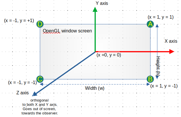
Figure 3: OpenGL default coordinate system (NDC - Normalized Device Coordinate)
OpenGL Coordinate System X Math-textbook Coordinate System
OpenGL default coordinate system should not be confused with the coordinate system commonly found in math and physics textbooks, where Z axis is the vertical axis, Y axis is the horizontal axis and the X axis is going from the screen twoards the screen observer (out of screen). The advantage of OpenGL coordinate system over the coordinate system used by textbooks is that 2D drawing requires just ignoring the Z axis, setting any Z coordinate to zero. If one does not like the OpenGL default coordinate system, it is possible to obtain the math textbook coordinate system just by applying affine rotation transform the OpenGL default coordinate system.
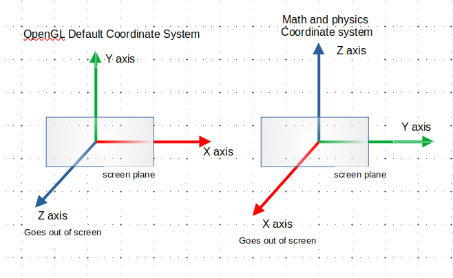
Figure 4: OpenGL coordinate system versus math or physics coordinate system.
The transform matrix that maps coordinates from the math and physics style coordinate system (M) to the OpenGL coordinate (C) can be obtained by:
\begin{equation} T_{M -> C} = \text{Rot}_x(-90) \cdot \text{Rot}_z(-90) \end{equation} \begin{equation} T_{M -> C} = \begin{bmatrix} 1 & 0 & 0 & 0 \\ 0 & 0 & 1 & 0 \\ 0 & -1 & 0 & 0 \\ 0 & 0 & 0 & 1 \end{bmatrix} \begin{bmatrix} 0 & 1 & 0 & 0 \\ -1 & 0 & 0 & 0 \\ 0 & 0 & 1 & 0 \\ 0 & 0 & 0 & 1 \end{bmatrix} \end{equation} \begin{equation} T_{M -> C} = \begin{bmatrix} 0 & 1 & 0 & 0 \\ 0 & 0 & 1 & 0 \\ 1 & 0 & 0 & 0 \\ 0 & 0 & 0 & 1 \end{bmatrix} \end{equation} \begin{equation} \underset{ \text{OpenGL Coord.} }{ \begin{bmatrix} x_o \\ y_o \\ z_o \\ 1 \end{bmatrix} } = \begin{bmatrix} 0 & 1 & 0 & 0 \\ 0 & 0 & 1 & 0 \\ 1 & 0 & 0 & 0 \\ 0 & 0 & 0 & 1 \end{bmatrix} \underset{ \text{Math Coord.} }{ \begin{bmatrix} x_m \\ y_m \\ z_m \\ 1 \end{bmatrix} } \end{equation}Where:
- \(Rot_x\) - Is the X axis rotation matrix.
- \(Rot_z\) - Is the Z axis rotation matrix.
- \(T_{M -> C}\) - Is the affine matrix transform that maps coordinates from math-and-physics coordinate system to OpenGL coordinate system.
- M - designates the coordinate system similar to the math-and-physics textbooks as in the right side of the previous picture.
- C - designates the openGL coordinate system.
Coordinates from math textbook style coordinate systems can be mapped to OpenGL by using the previous affine transform matrix.
\begin{equation} \begin{bmatrix} x_c \\ y_c \\ z_c \\ 1 \end{bmatrix} = T_{M -> C} \begin{bmatrix} x_m \\ y_m \\ z_m \\ 1 \end{bmatrix} \end{equation}With the previous equation it is possible to verify that the Y axis, vector (0, 1, 0) from the M coordinate system corresponds to the axis X (1, 0, 0) in the openGL (C) coordinate system.
\begin{equation} \begin{bmatrix} 1 \\ 0 \\ 0 \\ 1 \end{bmatrix} = \begin{bmatrix} 0 & 1 & 0 & 0 \\ 0 & 0 & 1 & 0 \\ 1 & 0 & 0 & 0 \\ 0 & 0 & 0 & 1 \end{bmatrix} \begin{bmatrix} 0 \\ 1 \\ 0 \\ 1 \end{bmatrix} \end{equation}The same procedure can be applied to X axis in (M) coordinate system, which is mapped to Z axis in OpenGL coordinate system and to Z axis from (M) coordinate system which is mapped to Y axis in OpenGL coordinate system.
Alternative Approach - using basis vectors
The rotation matrix that maps from math and physics reference frame M to Opengl reference frame, designated as C, is a matrix whose columns are the basis vectors (unit vectors) of each axis of reference frame M expressed in coordinates of reference frame C.
\begin{equation} ^C\hat{X}_M = \begin{pmatrix} 0 \\ 0 \\ 1 \end{pmatrix} \quad ^C\hat{Y}_M = \begin{pmatrix} 1 \\ 0 \\ 0 \end{pmatrix} \quad ^C\hat{Z}_M = \begin{pmatrix} 0 \\ 1 \\ 0 \end{pmatrix} \end{equation}Where:
- \(^C\hat{X}_M\) - is the X axis basis vector of frame M expressed in coordinates of reference frame C (OpenGL reference frame).
- \(^C\hat{Y}_M\) - is the Y axis basis vector of frame M expressed in coordinates of reference frame C (OpenGL reference frame).
- \(^C\hat{Z}_M\) - is the Z axis basis vector of frame M expressed in coordinates of reference frame C (OpenGL reference frame).
So, the rotation matrix that maps from frame M to frame C becomes:
\begin{equation} \boxed{ {}^{C}_{M}R = \begin{pmatrix} ^C\hat{X}_M & ^C\hat{Y}_M & ^C\hat{Z}_M \end{pmatrix} = \begin{pmatrix} 0 & 1 & 0 \\ 0 & 0 & 1 \\ 1 & 0 & 0 \\ \end{pmatrix} } \end{equation}The homogenous 4 x 4 by matrix that maps from M frame M to frame C (OpengL frame) can be obtained as follow:
\begin{equation} \boxed{ {}^{C}_{M}T = \begin{pmatrix} {}^{C}_{M}R & \boldsymbol{0}_{3 \times 1} \\ \boldsymbol{0}_{1 \times 3} & 1 \end{pmatrix} = \begin{pmatrix} 0 & 1 & 0 & 0 \\ 0 & 0 & 1 & 0 \\ 1 & 0 & 0 & 0 \\ 0 & 0 & 0 & 1 \end{pmatrix} } \end{equation}Coordinate System positions from other computer graphics APIS
The following diagram shows the possible default coordinate systems positions from many computer graphics APIS:
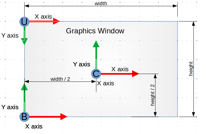
Figure 5: Default coordinate systems positions
- (C) => Center of display screen
- Default position of OpenGL NDC coordinate system (clip-space).
- (B) => Lower-left corner of display screen
- Default position of OpenGL screen coordinate system
- (U) => Upper-left corner of display screen
- => The Y axis is inverted, it is positive in the downward direction instead of upward direction.
- Default position of most 2D graphics APIs including: Html5 canvas; SVG; Java AWT 2D.
Transform matrix, \(T_{B \rightarrow U}\), that maps coordinates from lower-left corner (B) coordinate system to upper-left-corner coordinate system.
\begin{equation} T_{B \rightarrow U} = \begin{bmatrix} 1 & 0 & 0 \\ 0 & -1 & h \\ 0 & 0 & 1 \end{bmatrix} \end{equation}Transform matrix, \(T_{C \rightarrow U}\), that maps coordinates from (C) window-center coordinate system to upper-left corner (U) coordinate system. This transform is useful for drawing with origin on screen center when using gaphics APIs which the default coordinate system is located at the upper-left corner.
\begin{equation} T_{C \rightarrow U} = \begin{bmatrix} 1 & 0 & w/2 \\ 0 & -1 & h/2 \\ 0 & 0 & 1 \end{bmatrix} \end{equation} \begin{equation} V_U = T_{C \rightarrow U} \cdot V_C \end{equation} \begin{equation} \begin{bmatrix} x_u \\ y_u \\ 1 \end{bmatrix} = T_{C \rightarrow U} \begin{bmatrix} x_c \\ y_c \\ 1 \end{bmatrix} = \begin{bmatrix} x_c + w/2 \\ -y_c + h/2 \\ 1 \end{bmatrix} \end{equation}Transform matrix, \(T_{B \rightarrow C}\), that maps coordinates from lower-left corner (B) to screen-center origin, OpenGL normalized coordinate system (C).
\begin{equation} T_{B \rightarrow C} = \begin{bmatrix} 2/w & 0 & -1 \\ 0 & 2/h & -1 \\ 0 & 0 & 1 \end{bmatrix} \end{equation}The matrix transform, \(T_{C \rightarrow B}\), that maps from coordinate system C to coordinate system B can be computed as the inverse of \(T_{B \rightarrow C}\).
\begin{equation} T_{C \rightarrow B} = T_{B \rightarrow C}^{-1} = \begin{bmatrix} w/2 & 0 & w/2 \\ 0 & h/2 & h/2 \\ 0 & 0 & 1 \end{bmatrix} \end{equation}1.8.15 Column-Major X Row-major Matrices
OpenGL ES (embedded version of OpenGL) and WebGL APIs no longer support matrices in row-major order memory layout, where elements of rows are contiguous in memory. Instead, those APIs only support matrices in column-major memory layout, where elements of columns are contiguous in memory.
So, in modern OpenGL, the following API no longer works with boolean value 'true' that indicates that the matrix passed as a argument is in row-major oder format:
// WebGL API - (NO LONGER POSSIBLE =>> ERROR!)
gl.uniformMatrix4fv(u_model, true, matrix_in_row_major_order);

 // OpenGL ES - API (NO LONGER POSSIBLE!!!! =>> ERROR!!!)
 // Where u_model is a shader uniform variable
 glUniformMatrix4fv(u_model, 1, GL_TRUE,  matrix_in_row_major_order );
Now, only this following usage works:
// WebGL API
gl.uniformMatrix4fv(u_model, false, matrix_in_column_major_order);

 // OpenGL ES - API
 // Where u_model is a shader uniform variable
 glUniformMatrix4fv(u_model, 1, GL_FALSE,  matrix_in_column_major_order);
Further reading:
- In-place matrix transposition
- Row- and column-major order - Wikipedia
- Row major vs. column major, row vectors vs. column vectors | The ryg blog
- Geometry (Row Major vs Column Major Vector)
- Matlab - Row-Major and Column-Major Array Layouts
- Row major versus Column major layout of matrices
- Matrices, Handedness, Pre and Post Multiplication, Row vs Column Major, and Notations
- Memory layout of multi-dimensional arrays - Eli Bendersky's website
- Writing Efficient Code
Row-major matrices
Let the array T of type float[16], containing 16 32 bits floating point numbers, be a comumn-major matrix represeting some affine transform or projection transform.
T: float[16] = [ T[0], T[1], T[2], T[3], T[4], T[5], T[6], T[7], T[8], T[9], T[11], T[12], T[13], T[14], T[15] ]
The array T float[16], represents the following matrix in row-major order:
     /                           \
     |  T[00] T[01] T[02]  T[03]  |
     |  T[04] T[05] T[06]  T[07]  |
 T = |  T[08] T[09] T[10]  T[11]  |
     |  T[12] T[13] T[14]  T[15]  |
     \                            /

     /                             \
     |  A(1,1) A(1,2) A(1,3) A(1,4) |
     |  A(2,1) A(2,2) A(2,3) A(2,4) |
 T = |  A(3,1) A(3,2) A(3,3) A(3,4) |
     |  A(4,1) A(4,2) A(4,3) A(4,4) |
     \                             /

It follows that:

  T[00] = A(1,1) ; T[01] = A(1,2) ; T[02] = A(1,3) ; T[03] = A(1,4)
  T[04] = A(2,1) ; T[05] = A(2,2) ; T[06] = A(2,3) ; T[07] = A(2,4)
  T[08] = A(3,1) ; T[09] = A(3,2) ; T[10] = A(3,3) ; T[11] = A(3,4)
  T[12] = A(4,1) ; T[13] = A(4,2) ; T[14] = A(4,3) ; T[15] = A(4,4)


 T: float[16] = [  A(1,1), A(1,2), A(1,3), A(1,4)
                 , A(2,1), A(2,2), A(2,3), A(2,4)
                 , A(3,1), A(3,2), A(3,3), A(3,4)
                 , A(4,1), A(4,2), A(4,3), A(4,4)
               ];
Column-major matrices
Let the array T of type float[16], containing 16 32 bits floating point numbers, be a comumn-major matrix represeting some affine transform or projection transform.
T: float[16] = [ T[0], T[1], T[2], T[3], T[4], T[5], T[6], T[7], T[8], T[9], T[11], T[12], T[13], T[14], T[15] ]
The array T represents the following column-major matrix:
             Matrix in Column-Major Order
       _                                        _
      /                                          \
     +                                            +
T  = | COLUMN[0], COLUMN[1], COLUMN[2], COLUMN[3] |
     +                                            +
      \_                                        _/

    /                           \
    |  T[00] T[04] T[08]  T[12]  |
    |  T[01] T[05] T[09]  T[13]  |
T = |  T[02] T[06] T[10]  T[14]  |
    |  T[03] T[07] T[11]  T[15]  |
    \                            /

  Where:

                   | T[0] |               | T[4] |              | T[8]  |              | T[12] |
                   | T[1] |               | T[5] |              | T[9]  |              | T[13] |
       COLUMN[0] = | T[2] |   COLUMN[1] = | T[6] |  COLUMN[2] = | T[10] |  COLUMN[3] = | T[14] |
                   | T[3] |               | T[7] |              | T[11] |              | T[15] |
By applying the previous idea to this matrix, it is possible to find:
    /                             \
    |  A(1,1) A(1,2) A(1,3) A(1,4) |
    |  A(2,1) A(2,2) A(2,3) A(2,4) |
T = |  A(3,1) A(3,2) A(3,3) A(3,4) |
    |  A(4,1) A(4,2) A(4,3) A(4,4) |
    \                             /

T[00] = A(1,1) ; T[01] = A(2,1) ; T[02] = A(3,1) ; T[03] = A(4,1)
T[04] = A(1,2) ; T[05] = A(2,2) ; T[06] = A(3,2) ; T[07] = A(4,2)
T[08] = A(1,3) ; T[09] = A(2,3) ; T[10] = A(3,3) ; T[11] = A(4,3)
T[12] = A(1,4) ; T[13] = A(2,4) ; T[14] = A(3,4) ; T[15] = A(4,4)


T: float[16] = [  A(1,1), A(2,1), A(3,1), A(4,1)
                , A(1,2), A(2,2), A(3,2), A(4,2)
                , A(1,3), A(2,3), A(3,3), A(4,3)
                , A(1,3), A(2,4), A(3,4), A(4,4)
              ];
The array T can be converted to a matrix by using the next formula:
//----------------------------------//
// Matrix using 1 as initial index  //
//----------------------------------//
// Line 1
A(1, 1) = T[0]
A(1, 2) = T[4]
A(1, 3) = T[8]
A(1, 4) = T[12]
// Line 2
A(2, 1) = T[1]
A(2, 2) = T[5]
A(2, 3) = T[9]
A(2, 4) = T[13]
// Line 3
A(3, 1) = T[2]
A(3, 2) = T[6]
A(3, 3) = T[10]
A(3, 4) = T[14]
// Line 4
A(4, 1) = T[3]
A(4, 2) = T[7]
A(4, 3) = T[11]
A(4, 4) = T[15]

//----------------------------------//
// Matrix using 0 as initial index  //
//----------------------------------//
// Line 1
A(0, 0) = T[0]
A(0, 1) = T[4]
A(0, 2) = T[8]
A(0, 3) = T[12]
// Line 2
A(1, 0) = T[1]
A(1, 1) = T[5]
A(1, 2) = T[9]
A(1, 3) = T[13]
// Line 3
A(2, 0) = T[2]
A(2, 1) = T[6]
A(2, 2) = T[10]
A(2, 3) = T[14]
// Line 4
A(3, 0) = T[3]
A(3, 1) = T[7]
A(3, 2) = T[11]
A(3, 3) = T[15]
Example: Given the translation matrix T
     | 1  0  0  tx |
     | 0  1  0  ty |
 T = | 0  0  1  tz |
     | 0  0  0   1 |

 T[00] = A(1,1) = 1 ; T[01] = A(2,1) = 0 ; T[02] = A(3,1) = 0 ; T[03] = A(4,1) = 0 (column 1)
 T[04] = A(1,2) = 0 ; T[05] = A(2,2) = 1 ; T[06] = A(3,2) = 0 ; T[07] = A(4,2) = 0 (column 2)
 T[08] = A(1,3) = 0 ; T[09] = A(2,3) = 0 ; T[10] = A(3,3) = 1 ; T[11] = A(4,3) = 0 (column 3)
 T[12] = A(1,4) = tx; T[13] = A(2,4) = ty; T[14] = A(3,4) = tz; T[15] = A(4,4) = 1 (column 4)

Hence,

 T: float[16] = {  1,  0,  0,  0
                 , 0,  1,  0,  0
                 , 0,  0,  1,  0
                 , tx, ty, tz, 1 };

 T: float[16] = { 1,  0,  0,  0, 0,  1,  0,  0, 0,  0,  1,  0, tx, ty, tz, 1 }

 gl.uniformMatrix4fv(u_model, false, T);
This matrix in column-major order is represented as:
                                | 1   0   0  0 |
                                | 0   1   0  0 |
T             =  TRANSPOSE(T) = | 0   0   1  0 |
 column-major                   | tx ty  tz  1 |
1.8.16 Quaternions
Quaternions are a generalization of complex numbers, that was proposed and formulated by the irish mathematician and physicist William Rowan Hamilton, in 1843. This mathematical construct provides a convenient notation for expressing rotation and has a broad range of applications, including computer graphics, computer vision, robotics, orbital mechanics, aerospace and flight dynamics.
A quaternion q is defined as:
\begin{equation} q = w + x \cdot i + y \cdot j + z \cdot k \end{equation}- Where:
- w, x, y, z are real numbers.
- w => is the quaternion's real (scalar) component.
- [x, y, z] => is the quaternion's vector componet
- i, j, k are unit vectors (basis elements) that satisfies a set of properties.
The quaternion q can be represented in the following manner:
\begin{align*} q &= [w, x, y, z] \quad & \text{Tuple representation} \\ q &= (u, \vec{v}) \quad & \text{Scalar/vector representation} \\ \end{align*}- Where:
- \(\vec{v} = [x, y, z]\) is the quaternion vector component.
The quaternion unit vectors or basis elements satifies the following properties:
\begin{equation} i^2 = j^2 = k^2 = i \cdot j \cdot k = -1 \end{equation}And also:
\begin{align*} i \cdot j = k & \quad & j \cdot i = -k \\ j \cdot k = i & \quad & k \cdot j = -i \\ k \cdot i = j & \quad & i \cdot k = -j \\ \end{align*}Types of Quaternion
- Real quaternion
Real quaternion, is a quaterion which all elements of vector components are zero.
\begin{equation} q = w + 0 \cdot i + 0 \cdot j + 0 \cdot k \end{equation}- Pure quaternion
A pure quaternion, has the real part equal to zero. It can represent a vector in the space.
\begin{equation} q = 0 + x \cdot i + y \cdot j + z \cdot k \end{equation}- Unit quaternion
A quaternion which the norm or magnitude is equal to one.
\begin{equation} || q || = 1 \end{equation}- Identity quaternion
An identity quaternion when multiplied by another quaternion results in no rotation.
\begin{equation} q_i = 1 + 0 \cdot i + 0 \cdot j + 0 \cdot k \end{equation}In similar way to identity matrices, the following is valid:
\begin{equation} q_i \cdot q_a = q_a \cdot q_i = q_a \end{equation}Quaternion Conjugate
The conjugate of a quaternion, \(q^*\), is defined as:
\begin{equation} q^{*} = w - \vec{v} = w - (x \cdot i + y \cdot j + z \cdot k) = w + (-x) i + (-y) j + (-z) k \end{equation}Inverse Quaternion \(q^{-1}\)
\begin{equation} q^{-1} = \frac{q^{*}}{ || q ||^2 } \end{equation}The inverse quaternion satifies the following equality:
\begin{equation} q^{-1} \cdot q = q \cdot q^{-1} = 1 \end{equation}Quaternion Norm
The norm (magnitude) of a quaternion is given by:
\begin{equation} || q ||^2 = q \cdot q^{*} = w^2 + x^2 + y^2 + z^2 \end{equation}Unit quaternion
An unit quaternion \(q_u\) has norm equal to one.
\begin{equation} || q_u || = 1 \end{equation}An unit quaternion is equal to its conjugate:
\begin{equation} q^* = q^{-1} \end{equation}Quaternion Dot Product
A quaternion dot product is similar to vector dot product. The quaternion dot product between two quaternions q1 and q2 is defined as the sum of the product between the quaternions components.
\begin{equation} \text{dotquat}(q_1, q_2) = q_1 \cdot q_2 = w_1 \cdot w_2 + x_1 \cdot x_2 + y_1 \cdot y_2 + z_1 \cdot z_2 \end{equation}Angle between two quaternion
The angle between two quaternions q1 and q2 is defined as:
\begin{equation} \cos \theta = \frac{ q_1 \cdot q_2 }{ || q_1 || \cdot || q_2 || } = \frac{ \text{dotquat}(q_1, q_2) }{ \text{norm}( q_1) \cdot \text{norm}(q_2) } = \frac{ w_1 \cdot w_2 + x_1 \cdot x_2 + y_1 \cdot y_2 + z_1 \cdot z_2 }{ || q_1 || \cdot || q_2 || } \end{equation}Quaternion Sum
The sum of two quaternions q1 and q2 is:
\begin{equation} q_1 + q_2 = (w_1 + w_2) + (x_1 + x_2) i + (y_1 + y_2)j + (z_1 + z_2) k \end{equation}Quaternion Product (a.k.a Hamilton Product)
The product p of two quaternons q1 and q2 can be computed as:
- Where:
- p is the quaternion product between q1 and q2
- \(\vec{v_1} \cdot \vec{v_2}\) is the scalar product between \(\vec{v_1}\) and \(\vec{v_2}\).
- \(\vec{v1} \times \vec{v_2}\) is the cross product between \(\vec{v_1}\) and \(\vec{v_2}\).
- \(p_v\) is the vector component of p
- \(p_w\) is the scalar/real component of p.
The components of vector p are:
\begin{align*} p_w &= w_1 \cdot w_2 - \vec{v_1} \cdot \vec{v_2} \\ p_v &= w_1 \cdot \vec{v_2} + w_2 \cdot \vec{v_1} + \vec{v1} \times \vec{v_2} \\ \end{align*}The quaternion product is non commuative, as a result, the following holds:
\begin{equation} q_1 \cdot q_2 \neq q_2 \cdot q_2 \end{equation}The quaternion product satifies the following properties:
\begin{align*} || q_1 \cdot q_2 || &= ||q_1|| \cdot || q_2 || \\ (q_1 \cdot q_2)^* &= q_2^* \cdot q_1^* \end{align*}Quaternion product between pure quaternions
The product between two pure quaternions yields the dot product and cross simultaneously, the dot product as the real part of the operation result and cross product as the vector part of the result.
\begin{equation} p \cdot q = - (p \cdot q) + (p \times q) \end{equation}Where:
- Note: A pure quaternion, is the same as space vector, the real part is zero, w = 0.
- \(p = 0 + x_p \cdot i + y_p \cdot j + z_p \cdot k\)
- \(q = 0 + x_q \cdot i + y_q \cdot j + z_q \cdot k\)
- \(p \cdot q\) is the dot product between the vector parts of p and q.
- \(p \times q\) is the cross product (vector product) between p and q.
Quaternion division (MATH432 - page 11)
The division between two quaternions q1 and q2 is defined as:
\begin{equation} \frac{q_1}{q_2} = \frac{q_1 \cdot q_2^* }{ || q_2 ||^2 } = \frac{1}{ || q_2 ||^2 } ( q_1 \cdot q_2^* ) \end{equation}Quaternion product using matrices representation
The product of two quaternions q1 and q2 can be computed in a more convenient and faster way by using matrices and column vectors multiplication, instead of dot product and cross product.
Let \([q]_v\) be the vector column representation of a quaternion:
\begin{equation} [q]_v = \begin{bmatrix} w \\ x \\ y \\ z \end{bmatrix} \end{equation}Let \([q]_m\) be the following matrix representation of a quaternion:
\begin{equation} [q]_m = \begin{bmatrix} w & -x & -y & -z \\ x & w & -z & y \\ y & z & w & -x \\ z & -y & x & w \\ \end{bmatrix} \end{equation}The quaternion product between q1 and q2, designated by \([q_r]_v\), can be expressed as a matrix-column vector multiplication, which is best suitable for a computer implementation.
\begin{equation} [q_r]_v = q_1 \cdot q_2 = [q_1]_m \cdot [q_2]_v = \begin{bmatrix} w_1 & -x_1 & -y_1 & -z_1 \\ x_1 & w_1 & -z_1 & y_1 \\ y_1 & z_1 & w_1 & -x_1 \\ z_1 & -y_1 & x_1 & w_1 \\ \end{bmatrix} \begin{bmatrix} w_2 \\ x_2 \\ y_2 \\ z_2 \\ \end{bmatrix} \end{equation}By performing the previous matrix multiplication, the quaternion product becomes:
\begin{equation} [q_r]_v = q_1 \cdot q_2 = \begin{bmatrix} w_1 \cdot w_2 - x_1 \cdot x_2 - y_1 \cdot y_2 - z_1 \cdot z_2 \\ x_1 \cdot w_2 + w_1 \cdot x_2 - z_1 \cdot y_2 + y_1 \cdot z_2 \\ y_1 \cdot w_2 + z_1 \cdot x_2 + w_1 \cdot y_2 - x_1 \cdot z_2 \\ z_1 \cdot w_2 - y_1 \cdot x_2 + x_1 \cdot y_2 + w_1 \cdot z_2 \\ \end{bmatrix} \end{equation}Rotation Quaternion
A rotation around an axis \(\hat{n}\) (unit vector) by angle \(\theta\) can be encoded by quaternion \(q_r\):
\begin{equation} q_r = \cos \frac{\theta}{2} + \sin \frac{\theta}{2} \cdot \hat{n} = \cos \frac{\theta}{2} + \sin \frac{\theta}{2} ( x_n \cdot i + y_n \cdot j + z_n \cdot k ) \end{equation}- Where:
- \(\hat{n}\) is a unit vector.
- \(\hat{n} = x_n \cdot i + y_n \cdot j + z_n \cdot k\)
- \(|| \hat{n} || = 1\)
The norm of quaternion \(q_r = 1\), thus the following holds:
\begin{equation} || q_r || = 1 \end{equation}The coordinate transformation from a vector in reference frame A to a reference frame B, obtained by the rotation of coordinate frame A around a unit vector \(\hat{n}\) can be computed as:
\begin{equation} q_B = q_r \cdot q_A \cdot q_r^{-1} = q_r \cdot q_A \cdot q_r^{*} \end{equation}Where:
- \(q_A\) is the coordinate of a vector in the reference frame A (aka coordinate system, aka coordinate frame).
- \(q_B\) is the coordinate of a the same vector in the reference frame B.
- \(q_A = 0 + x_A \cdot i + y_A \cdot j + z_A \cdot k\)
- \(q_B = 0 + x_B \cdot i + y_B \cdot j + z_B \cdot k\)
The previous rotation coordinate transformation can be determined in a more efficient way by applying the following algorithm. (The-Ryg-Blog)
\begin{eqnarray*} v_t &=& 2 ( v_r \times v_a) \\ q_B &=& v_A + w_r \cdot v_t + v_r \times v_t \end{eqnarray*}Where:
- \([ Q ]_w\) - real part of a quaternion Q
- \([ Q ]_v\) - vector part of a quaterion Q
- \(w_r = \cos ( \theta / 2)\) - real part of rotation quaternion \(q_r\)
- \(v_r = \hat{n} \cdot \sin( \theta / 2 )\) - vector part of rotation quaternion \(q_r\)
- \(v_B\) - vector part of quaternion \(q_B\)
- \(v_A\) - Vector part of quaternion \(q_A\)
- \(v_r \times v_a\) - Cross product between those two vectors.
Determining rotation and axis from a normalized quaternion
Supposing that the components (w, x, y, z) of normalized quaternion q are known. The represented rotation angle, \(\theta\) and rotation axis (a.k.a orientation) vector, \(\hat{n} = [x_n \quad y_n \quad z_n]\), can be determined in the following way.
Rotation quaternion (known: x, y, z, w)
\begin{eqnarray*} q &=& w + x \cdot i + y \cdot j + z \cdot k \\ &=& \cos \frac{\theta}{2} + \sin \frac{\theta}{2} \hat{n} \\ &=& \cos \frac{\theta}{2} + \sin \frac{\theta}{2} (x_n \cdot i + y_n \cdot j + z_n \cdot k) \\ \end{eqnarray*}Rotation angle \(\theta\)
\begin{equation} \theta = 2 \text{atan2}( || \vec{v} ||, w ) = 2 \text{atan2}( \sqrt{x^2 + y^2 + z^2} , w ) \end{equation}Rotation axis: \(\hat{n} = x_n \cdot i + y_n \cdot j + z_n \cdot k\)
\begin{eqnarray*} x_n &=& x / \sqrt{1 - w^2} \\ y_n &=& y / \sqrt{1 - w^2} \\ z_n &=& z / \sqrt{1 - w^2} \\ \end{eqnarray*}Where:
- Atan2(Y, X) is the 2-argument tangent function which determines the angle quadrant.
- \(q = w + x \cdot i + y \cdot j + z \cdot k\) - is a unitary quaternion, which components x, y and z are assumed to be known. The quaternion q is presumed to be normalized.
- \(\theta\) is the rotation angle. Assumed to be unknown.
- \(\hat{n}\) - is the rotation axis vector. Also assumed to be
unknown, which components are \(x_n\), \(y_n\) and \(z_n\).
- \(\hat{n} = 0 + x_n \cdot i + y_n + \cdot j + z_n \cdot k\)
Quaternion to rotation matrix conversion
The rotation matrix that transforms coordinates from reference frame A to reference frame B can be computed as: (Moti Ben-Ari - Wizmann), (Jernej Barbic)
\begin{equation} R_n = \begin{bmatrix} a^2 + b^2 - c^2 - d^2 & 2 (b \cdot c - a \cdot d) & 2 (b \cdot d + a \cdot c) \\ 2 (b \cdot c + a \cdot d ) & a^2 - b^2 + c^2 -d^2 & 2 ( c \cdot d - a \cdot b ) \\ 2 ( b \cdot d - a \cdot c ) & 2 ( c \cdot d + a \cdot b ) & a^2 - b^2 - c^2 + d^2 \\ \end{bmatrix} \end{equation}Where:
- a, b, c, d are the components of the unit quaternion \(q_r\)
- \(a = \cos( \theta / 2)\)
- \(b = x_n \cdot \sin (\theta / 2)\)
- \(c = y_n \cdot \sin (\theta / 2)\)
- \(d = z_n \cdot \sin (\theta / 2)\)
The matrix \(R_n\) can also be simplified to: (Moti Ben-Ari - Wizmann)
\begin{equation} R_n = 2 \begin{bmatrix} a^2 + b^2 - 1/2 & b \cdot c - a \cdot d & a \cdot c + b \cdot d \\ a \cdot d + b \cdot c & a^2 + c^2 - 1/2 & c \cdot d - a \cdot b \\ b \cdot d - a \cdot c & a \cdot b + c \cdot d & a^2 + d^2 - 1/2 \\ \end{bmatrix} \end{equation}Coordinates from frame A can be turned into coordinates from frame B by performing the following matrix multiplication.
\begin{equation} \begin{bmatrix} x_B \\ y_B \\ z_B \end{bmatrix} = R_n \begin{bmatrix} x_A \\ y_A \\ z_A \end{bmatrix} \end{equation}From the previous matrix \(R_n\) it is possible to determine the yaw-pitch-roll (Z-X-Y) Euler's angles. (chrobotics)
\begin{eqnarray*} \phi &=& \arctan\left( \frac{ 2 a \cdot b + 2 c \cdot d } { a^2 - b^2 - c^2 + d^2 } \right ) \\ \theta &=& -\arcsin\left( 2 b \cdot d - 2 a \cdot c \right ) \\ \psi &=& \arctan\left( \frac{ 2 a \cdot d + 2 b \cdot c}{ a^2 + b^2 - c^2 - d^2 } \right ) \\ \end{eqnarray*}Where:
- \(\phi\) - is the yaw angle
- \(\theta\) - is the pitch angle
- \(\psi\) -is the roll angle
Quaternion to homogeneous coordinate rotation matrix
The matrix \(R_n\) can be converted to a homogenous coordinate form, \(T_n\), which is more convenient, since homogenous coordinate allows expressing translations in a similar fashion to rotation transformations, just as vector-matrix multiplication.
\begin{equation} T_n = \begin{bmatrix} a^2 + b^2 - c^2 - d^2 & 2 (b \cdot c - a \cdot d) & 2 (b \cdot d + a \cdot c) & 0 \\ 2 (b \cdot c + a \cdot d ) & a^2 - b^2 + c^2 -d^2 & 2 ( c \cdot d - a \cdot b ) & 0 \\ 2 ( b \cdot d - a \cdot c ) & 2 ( c \cdot d + a \cdot b ) & a^2 - b^2 - c^2 + d^2 & 0 \\ 0 & 0 & 0 & 1 \\ \end{bmatrix} \end{equation}Homogeneous coordinates from frame A can be turned into coordinates of frame B by using the following expression:
\begin{equation} \begin{bmatrix} x_B \\ y_B \\ z_B \\ 1 \end{bmatrix} = T_n \begin{bmatrix} x_A \\ y_A \\ z_A \\ 1 \end{bmatrix} \end{equation}Table with Useful Normalized Quaternions (Rotation Quaternions) - (Ogre3D Game Engine)
| w | x | y | z | Description | |
|---|---|---|---|---|---|
| 1 | 0 | 0 | 0 | Identity quaternion, represents no rotation. | |
| 0 | 1 | 0 | 0 | 180° (π radians) rotation around X axis | |
| 0 | 0 | 1 | 0 | 180° rotation around Y axis | |
| 0 | 0 | 0 | 1 | 180° rotation around Z axis. | |
| \(\sqrt{1/2}\) | \(\sqrt{1/2}\) | 0 | 0 | 90° rotation around X axis. | |
| \(\sqrt{1/2}\) | 0 | \(\sqrt{1/2}\) | 0 | 90° rotation around Y axis. | |
| \(\sqrt{1/2}\) | 0 | 0 | \(\sqrt{1/2}\) | 90° rotation around Z axis. | |
| \(\sqrt{1/2}\) | \(-\sqrt{1/2}\) | 0 | 0 | -90° rotation around X axis. | |
| \(\sqrt{1/2}\) | 0 | \(-\sqrt{1/2}\) | 0 | -90° rotation around Y axis. | |
| \(\sqrt{1/2}\) | 0 | 0 | \(-\sqrt{1/2}\) | -90° rotation around Z axis. | |
Note:
- \(\sqrt{1/2} = \sqrt{0.5} \approx 0.70710\)
- \(\pi = pi = \approx 3.14159265\)
Further Reading
Quaternions:
- Quaternions - Wikipedia
- Quaternions and spatial rotation
- History of Quaternions
- An algorithm for dividing quaternions [PAPER]
- Understanding Quaternions - ChRobotics
- Understanding Euler Angles - ChRobotics
- Quaternion Calculator - Energid / Actin Advanced Control For Robotics
- Note: Online calculator for Quaternions.
- A Tutorial on Euler Angles and Quaternions - Weizmann Institute of Science
- Quaternion Rotation Primer / Ogre3D Game Engine
- https://web.cs.ucdavis.edu/~amenta/3dphoto/quaternion.pdf
- quatinterp() - Quaternion interpolation between two quaternions - Matlab Aerospace Toolbox
- Maths - Quaternion Interpolation (SLERP) - Euclidianspace.com
- Understanding Quaternions - 3DGEP - 3D Game Engine Programming
- Quaternion - in computer animation
- Quaternion interpolation
- [PDF] Spherical Skinning withDual-Quaternions and QTangents - Spherical Skinning withDual-Quaternions and QTangentsIvo Zoltan FreyCrytek R&D
- [PDF] Orientation & Quaternions - University of Texas
- [PDF] Quaternions: From Classical Mechanics to Computer Graphics, and Beyond
- [PDF] QUATERNION-BASED AUTOPILOT FOR DODECACOPTERS - PART I
- [PDF] Introduction into quaternions for spacecraft attitude representation
- https://github.com/mattlisle/quaternion-ukf (Kalman-Filter and Quaternion)
- "This implementation of a UKF for tracking orientation of a drone with gyro and accelerometer data follows closely that described in the paper "A Quaternion-based Unscented Kalman Filter for Orientation Tracking" by Edgar Kraft."
- https://stackoverflow.com/questions/tagged/quaternions
- https://stackoverflow.com/questions/tagged/gyroscope
Dual Quaternion:
- Dual quaternions are a combination of quaternions and dual numbers. Unlike ordinary quaternions, which can only express rotation, dual quaternions can express both rotation and translation in a more concise and efficient way than transformation matrices. Some applications of this mathematical construct are: computer graphics; robotics; aerospace engineering and more.
- Dual Quaternions
- Feature guide » 2D and 3D transformations - Magnum Engine
- [PDF] - Paper: A Beginners Guide to Dual-Quaternions - What They Are, How They Work, and How to Use Them for 3D Character Hierarchies
- [PDF] - Paper: Modeling of Spacecraft-Mounted Robot Dynamics and Control Using Dual Quaternions
- [PDF] - Paper: Dual Quaternions for Rigid Transformation Blending
- [PDF] - Report: Dual Quaternions - Yan-Bin Jia
- Matalab File Exchange - Dual quaternion toolbox
Quaternion Computer Implementations:
- t::Quaternion - ROS Framework (C++)
- Qt5 C++ Framework - QQuaternion class (C++)
- Qt5 - Rotation Example
- MinGfx C++ - OpenGL Wrapper (C++)
- FQuat - Unreal Game Engine (C++)
- Brief: "Floating point quaternion that can represent a rotation about an axis in 3-D space."
- FTransform - Unreal Game Engine (C++)
- Brief: "Transform composed of Scale, Rotation (as a quaternion), and Translation."
- Note: It has three member variables: Rotation (class FQaut), Scale3D (FVector) and Translation (FVector).
- FRotator - Unreal Gamer Engine (C++)
- Brief: "Implements a container for rotation information. All rotation values are stored in degrees."
- Unity3D - Quaternion (C#, CSharp - Unity Game Engine)
- Brief: "Quaternions are used to represent rotations. They are compact, don't suffer from gimbal lock and can easily be interpolated. Unity internally uses Quaternions to represent all rotations. They are based on complex numbers and are not easy to understand intuitively. You almost never access or modify individual Quaternion components (x,y,z,w); most often you would just take existing rotations (e.g. from the Transform) and use them to construct new rotations (e.g. to smoothly interpolate between two rotations). The Quaternion functions that you use 99% of the time are: Quaternion.LookRotation, Quaternion.Angle, Quaternion.Euler, Quaternion.Slerp, Quaternion.FromToRotation, and Quaternion.identity. (The other functions are only for exotic uses.)"
- Magnum Graphics Library - Quaternion (C++)
- Quaternion Struct - Dotnet (C#)
- Octave - Quaternion Library (OCtave Language, akin to Matlab)
- Blender - MathUtils module
1.8.17 Quaternions - Combining Scale and Position
Quaternions (non-dual quaternions) can only encode and represent rotations around some orientation, which is not enough to specify position and scaling. As a result, quaternions rotation matrices need to be concatenated with translation and scaling transform matrices for computing an object's model transform matrix, which is often passed to a shader program via uniform variables.
Assuming that a rendered object has a transform member variable of type RendererTransform containing a a quaternion, for representing rotation; a scale vector and a position vector. The method get_transform() compute the rendered object transform matrix, which is the concatenation of rotation (quaternion), scaling and translation transforms. The model transform determined by get_transform() method can be passed to a shader uniform variable.
Note: Dual-quaternions, which are a combination of dual-numbers and ordinary quaternions, can express both rotation and translation.
- Class RendererTransform:
struct RenderTransform
{
      // Rotation quaternion
      // Set to identity quaternion by default.
      // Members. The quaternion has the fields (w, x, y, z)
      quaternion rotation {1.0, 0.0, 0.0};

      // Scale vector containing scales (sx, sy, sz) of axis (X, Y, Z)
      vec3 scale(1.0, 1.0, 1.0);

      // Contains object's position
      vec3 position(tx, ty, tz);

      // ??? Get overall (end result) transform matrix that
      // will be passed to shader uniform variable.
      mat4 get_transform() const { ????? }

      void translate(float dx, float dy, float dz)
      {
          this->position.x += dx;
          this->position.y += dy;
          this->position.z += dz;
      }

      void set_position(float x, float y, float z)
      {
          this->position.x = x;
          this->position.y = y;
          this->position.z = z;
      }

      void set_scale(float sx float sy, float sz)
      {
         this->scale.x = sx;
         this->scale.y = sy;
         this->scale.z = sz;
      }
};
The transforms are often applied in the following sequence, first scaling, then rotation and finally translation.
\begin{equation} T = T_t \cdot T_r \cdot T_s = \text{Translation} \cdot \text{Rotation} \cdot \text{Scaling} \end{equation}Where:
- T is the total transform matrix, which is the product between intermediate transforms and later can be passed to a shader uniform variable.
- \(T_s\) - is the scale transform, determined from the scale vector.
- \(T_t\) - is the translation transform, computed from the position vector.
- \(T_r\) - is the quaternion rotation transform.
Intermediate transforms:
- Translation affine transform form position vector.
- Scaling affine transform from scale vector.
- Rotation affine transform obtainted from rotation quaternion.
- Note: most linear algebrar or computer graphics math libraries provide subroutines (aka functions) or class methods for converting quaternions to 4x4 rotation matrices. Those libraries also provide subroutines for determining a quaternion's yaw, pitch and roll angles and constructing the quaternion from yaw, pitch and roll angles.
The end transform T is determined by concatenating all intermediate transforms:
\begin{equation} T = T_t \cdot T_r \cdot T_s \end{equation} \begin{equation} T = \begin{bmatrix} 1 & 0 & 0 & t_x \\ 0 & 1 & 0 & t_y \\ 0 & 0 & 1 & t_z \\ 0 & 0 & 0 & 1 \\ \end{bmatrix} \begin{bmatrix} a_{11} & a_{12} & a_{13} & 0 \\ a_{21} & a_{22} & a_{23} & 0 \\ a_{31} & a_{32} & a_{33} & 0 \\ 0 & 0 & 0 & 1 \\ \end{bmatrix} \begin{bmatrix} s_x & 0 & 0 & 0 \\ 0 & s_y & 0 & 0 \\ 0 & 0 & s_z & 0 \\ 0 & 0 & 0 & 1 \\ \end{bmatrix} \end{equation}Finally, the model transform becomes:
\begin{equation} T = \begin{bmatrix} s_x \cdot a_{11} & s_y \cdot a_{12} & s_z \cdot a_{13} & t_x \\ s_x \cdot a_{21} & s_y \cdot a_{22} & s_z \cdot a_{23} & t_y \\ s_x \cdot a_{31} & s_y \cdot a_{32} & s_z \cdot a_{33} & t_z \\ 0 & 0 & 0 & 1 \\ \end{bmatrix} \end{equation}Then, the algorithm for determing the object model matrix, designated by the transform T, could be written as the following pseudo-code:
mat4 RenderTransform::get_transform() const
{
    // Convert quaternion to a 4x4 rotation matrix (affine transform)
    mat4 model_transform = quaternion_to_rotation_transform( this->quaternion );

    // Multiply all elements of first column by X axis scale
    model_transform.comlumn[0] = scale.x * model_transform.column[0];
    // Multiply all elemnts of second column by Y axis scale
    model_transform.comlumn[1] = scale.y * model_transform.column[1];
    // Multiply all elemnts of third column by Z axis scale
    model_transform.comlumn[2] = scale.z * model_transform.column[2];

    // Set all elements of forth column as the 4x1  column vector
    // column4 = [position.x position.y position.z 1.0 ]
    model_transform.column[4] = vec4( position.x, position.y, position.z, 1.0f );

    return model_transform;
}
To rotate the rendered object, it is only necessary to multiply the quaternion variable, called 'rotation' by another quaternion. So, a C++-like pseudo-code for setting or adding a new rotation could be written as:
RenderTransform object_transform;

// Set a new rotation - overriding the old one.
void RenderTransform::set_rotation(float angle_radians, vec3 axis_direction)
{
    // Normalize axis
    vec3 axis = axis_direction.normalize();
    // Make explicit assumption the assumption that the quaternion is normalized.
    assert( norm(axis) ~= 1.0  );
    this->object_transform.quaternion = make_quaternion_from_AngleAxis(angle, axis);
}

// Add a new rotation, rotate the previous quaternion.
void RenderTransform::rotate(float angle_radians, vec3 axis_direction)
{
    vec3 axis = axis_direction.normalize();
    assert( norm(axis) ~= 1.0  );
    quaternon q = make_quaternion_from_AngleAxis(angle, axis);
    this->object_transform.quaternion = this->object_transform.quaternion * q;
}


// Set a new Yaw-Pitch-Roll Euler's angles rotation.
void RenderTransform::set_rotation_YRP(float yaw, float pitch, float roll)
{
    vec3 axis = axis_direction.normalize();
    assert( norm(axis) ~= 1.0  );
    quaternon q = make_quaternion_from_YAW_PITCH_ROLL(yaw, pitch, roll);
    assert( norm(q) ~= 1.0 );
    this->object_transform.quaternion = q;
}
See also:
- Performance of quaternions in the GPU - Metail Tech
- c++ - Matrix multiply with position, quaternion and scale components - Stack Overflow
- Rotating Objects Using Quaternions - Noick Bobic / Gamasutra
1.8.18 Quaternion in Julia Language
It is worth prototyping quaternion math in a numerically-oriented programming language such as Julia Language is helpful for understanding and validating the inner works of quaternion computations. This implementation of quaternion math represents quaternion as an array of four elements and uses a matrix representation for implemeting quaternion multiplication.
# Struct for storing quaternion
# q = w + x·i + y·j + z·k
struct quatp
   arr::Array{Float64,1}
end

function quat(x, y, z, w)
  return quatp([x ; y; z; w])
end

# Turns a quaternion into 4x4 matrix representation
function quat_to_mat4x4(q::quatp)
    w, x, y, z  = q.arr
    mat = [  w -x -y -z
           ; x  w -z  y
           ; y  z  w -x
           ; z -y x w ]
    return mat
 end

function Base.getproperty(q::quatp, sym::Symbol)
    if sym == :arr
        return getfield(q, :arr)
    elseif sym == :w
        return getfield(q, :arr)[1]
    elseif sym == :x
        return getfield(q, :arr)[2]
    elseif sym == :y
        return getfield(q, :arr)[3]
    elseif sym == :z
        return getfield(q, :arr)[4]
    elseif sym == :v
        # Return only the quaternion (vector part)
        return getfield(q, :arr)[2:end]
    end
end

# Norm - quaternion magnitude, akin to vector norm
function norm(q::quatp)
   w, x, y, z = q.arr
   return sqrt(w * w + x * x + y * y + z * z)
end

# Conjugate of a quaternion
function conj(q::quatp)
  return quat(q.w, -q.x, -q.y, -q.z)
end

# Inverse of quaternion q^-1
function Base.:inv(q::quatp)
   w, x, y, z = q.arr
   norm_square =  w * w +  x * x + y * y + z * z
   return  quat(w, -x, -y, -z) / norm_square
end

# Quaternion sum
Base.:+(q1::quatp, q2::quatp) = quat(q1.w + q2.w, q1.x + q2.x, q1.y + q2.y, q1.z + q2.z)
Base.:-(q1::quatp, q2::quatp) = quat(q1.w - q2.w, q1.x - q2.x, q1.y - q2.y, q1.z - q2.z)

Base.:+(q::quatp,   w::Float64) = quat(w + q.w, q.x, q.y, q.z)
Base.:+(w::Float64, q::quatp  ) = quat(w + q.w, q.x, q.y, q.z)
Base.:-(q::quatp,   w::Float64) = quat(q.w - w, q.x, q.y, q.z)

# Mutliplication => scalar X quaternion
Base.:*(a::Float64, q::quatp) = quat( a * q.w, a * q.x, a * q.y, a * q.z)
Base.:*(q::quatp, a::Float64) = quat( a * q.w, a * q.x, a * q.y, a * q.z)

Base.:/(q::quatp, a::Float64) = quat( q.w / a, q.x / a, q.y / a, q.z / a)

# Quaternion multiplication / product
Base.:*(q1::quatp, q2::quatp) = begin
     A = quat_to_mat4x4(q1)
     return quatp( A * q2.arr )
end

# Unit quaternions i, j, k
const i = quat(0.0, 1.0, 0.0, 0.0)
const j = quat(0.0, 0.0, 1.0, 0.0)
const k = quat(0.0, 0.0, 0.0, 1.0)


# Obtain a rotation quaternion that represents a rotation
# by some angle around some direction (normalized vector 'vec')
# => The angle is given in degrees.
function rot_quat(angle::Float64, vec)
   # Normalize vector vec and store the result in v
   xv, yv, zv = vec
   x, y, z = vec / sqrt( xv * xv + yv * yv + zv * zv )
   S = cosd(angle / 2)
   C = sind(angle / 2)
   return quat(C, S * x, S * y, S * z)
end

## Vector cross product VA x VB of two column vectors (3 x 1)
function cross(va, vb)
     x, y, z = va
     T = [ 0 -z y ; z 0 -x; -y x 0]
     T * vb
 end

## Apply a rotation quaternion to a vector (column vector 3 x 1)
##  =>> Vector 3 rows and 1 column
## Algorithm from:
#     =>> https://fgiesen.wordpress.com/2019/02/09/rotating-a-single-vector-using-a-quaternion/
function apply_rot(qr::quatp, va)
   wr = qr.w # Scalar/real part of rotation quaternion
   vr = qr.v # Vector part of rotation quaternion
   vt = 2 * cross(vr, va)
   vb = va + wr * vt + cross(vr, vt)
   return vb
end

# Obtain a rotation matrix - that represents rotation
# around an arbitrary axis (vector)
# Note: The angle is should be in degrees.
#
function make_rotmat(angle::Float64, vec)
   # Normalize vector vec and store components in x, y, z
   x, y, z = vec
   x, y, z = vec / sqrt( x * x + y * y + z * z )
   # sin and cos caching
   C = cosd(angle / 2)
   S = sind(angle / 2)
   # Parameters a, b, c, d => Components of the rotation
   # quaternion
   a = C
   b = x * S
   c = y * S
   d = z * S
   # rotation matrix
   mat = [
        ( a^2 + b^2 - c^2 - d^2 )  ( 2 * (b * c - a * d )  ) ( 2 * (b * d + a * c)   )  0
     ;  ( 2 * (b * c + a * d)   )  ( a^2 - b^2 + c^2 - d^2 ) ( 2 * (c * d - a * b)   )  0
     ;  ( 2 * (b * d - a * c)   )  ( 2 * (c * d + a * b)   ) ( a^2 - b^2 - c^2 + d^2 )  0
     ;  0                          0                         0                          1
   ]
   return mat
end
Quaternion components:
# Construct a quaternion

julia> q = quat(10.5, -25.1, 4.5, 5.6)
quatp([10.5, -25.1, 4.5, 5.6])

julia> q.w # Real part
10.5

julia> q.x # Imaginary part - i axis component
-25.1

julia> q.y # Imaginary part - j axis component
4.5

julia> q.z # Imaginary part - k axis component (Z axis)
5.6

julia> q.arr # Internal array data representation
4-element Array{Float64,1}:
  10.5
 -25.1
   4.5
   5.6

julia> q.v # Vector component (i, j, k) components only
3-element Array{Float64,1}:
 -25.1
   4.5
   5.6
Quaternion conjugate and inverse:
julia> q = quat(1.0, 2.0, 3.0, 4.0)
quatp([1.0, 2.0, 3.0, 4.0])

julia> inv(q)
quatp([0.03333333333333333, -0.06666666666666667, -0.1, -0.13333333333333333])

# Expected (-1.0)
julia> q * inv(q)
quatp([1.0, 0.0, 0.0, 0.0])

# Expected (-1.0)
julia> inv(q) * q
quatp([1.0, -5.551115123125783e-17, -6.938893903907228e-18, 5.551115123125783e-17])
Normalize a quaternion:
# Expected normalized to be: (w = 0.18257, x = 0.36515, y = 0.54772, z = 0.7303)
# Test case from: Matlab Robotics Toolbox - https://www.mathworks.com/help/robotics/ref/quaternion.normalize.html

 julia> q = quat(1.0, 2.0, 3.0, 4.0)
 quatp([1.0, 2.0, 3.0, 4.0])

 julia> qn = normalize(q)
 quatp([0.18257418583505536, 0.3651483716701107, 0.5477225575051661, 0.7302967433402214])

 julia> norm(qn)
 0.9999999999999999
Test case 1 - for quaternion multiplication:
- Test quaternion laws:
- Expected: i * i = j * j = k * k = -1
- Expected: i * j = k
- Expected: j * k = i
- Expected: k * i = j
- Expected: j * i = -k
# ---- Show components i, j, k --------#

julia> i
quatp([0.0, 1.0, 0.0, 0.0])

julia> j
quatp([0.0, 0.0, 1.0, 0.0])

julia> k
quatp([0.0, 0.0, 0.0, 1.0])

# ----- Check multiplication of i, j, k by themselves -----------#
#

julia> i * i # Expected -1 or (-1) + 0·i + 0·j + 0·k
quatp([-1.0, 0.0, 0.0, 0.0])

julia> j * j # Expected -1
quatp([-1.0, 0.0, 0.0, 0.0])

julia> k * k # Expected -1
quatp([-1.0, 0.0, 0.0, 0.0])

#------- Check multiplication i * j, j * k, k * i and j * i
#
julia> i * j # Expected k
quatp([0.0, 0.0, 0.0, 1.0])

julia> j * i # Expected -k
quatp([0.0, 0.0, 0.0, -1.0])

julia> k * i # Expected j
quatp([0.0, 0.0, 1.0, 0.0])

julia> i * k # Expected -j
quatp([0.0, 0.0, -1.0, 0.0])
Test case 2 - for quaternion multiplication:
- From: Matlab Aerospace Toolbox
- q1 = [ 1.0 0.0 1.0 0.00 ]
- q2 = [ 1.0 0.5 0.5 0.75 ]
- Expected result =>> q1 * q2 = [ 0.5 1.25 1.5 0.25 ]
# -------- Test A ------------------------#
julia> q1 = quat(1.0, 0.0, 1.0, 0.0)
quatp([1.0, 0.0, 1.0, 0.0])

julia> q2 = quat(1.0, 0.5, 0.5, 0.75)
quatp([1.0, 0.5, 0.5, 0.75])

# ------- Test B ---------------------#

julia> q1 = 1.0 + 0.0i + 1.0j + 0.0k
quatp([1.0, 0.0, 1.0, 0.0])

julia> q2 = 1.0 + 0.5i + 0.5j + 0.75k
quatp([1.0, 0.5, 0.5, 0.75])

julia> q1 * q2
quatp([0.5, 1.25, 1.5, 0.25])
Test case 3 - for quaternion multiplication:
- From: Maplesoft - Quaternion
- q1 = ( -6) + (-8)i + (-5)j + 7k
- q2 = (-14) + (-12)i + (-19)j + (-17)k
- Expected: q1 * q2 = 12 + 402i + (-36)j + 96k
- Expected: q2 * q1 = 12 + (-34)i + 404j + (-88)k
- Expected: q2 + q1 = (-20) + (-20)i + (-24)j + (-10)k
julia> q1 = -6.0 + -8.0i + -5.0j + 7.0k
quatp([-6.0, -8.0, -5.0, 7.0])

julia> q2 = -14.0 + -12.0i + -19.0j + -17.0k
quatp([-14.0, -12.0, -19.0, -17.0])

julia> q1 * q2
quatp([12.0, 402.0, -36.0, 96.0])

julia> q2 * q1
quatp([12.0, -34.0, 404.0, -88.0])

julia> q1 + q2
quatp([-20.0, -20.0, -24.0, -10.0])

julia> q2 + q1
quatp([-20.0, -20.0, -24.0, -10.0])
Test algorithm - make_rotmat that computes rotation matrices around an arbitrary axis:
Define functions for computing rotation matrices:
# Rotation around X axis
function rot_x(angle::Float64)
   C = cosd(angle)
   S = sind(angle)
   return [  1   0   0  0
           ; 0   C  -S  0
           ; 0   S   C  0
           ; 0   0   0  1
          ]
end

# Rotation around X axis
function rot_y(angle::Float64)
   c = cosd(angle)
   s = sind(angle)
   return [  c   0   s  0
           ; 0   1   0  0
           ;-s   0   c  0
           ; 0   0   0  1
          ]
end

# Returns homogeneous rotation matrix around Z axis
# => The angle must be in degrees, not radians
function rot_z(angle::Float64)
   c = cosd(angle)
   s = sind(angle)
   return [  c  -s  0  0
           ; s   c  0  0
           ; 0   0  1  0
           ; 0   0  0  1
          ]
end
Test rotation matrices:
const axis_x = [1.0 0.0 0.0]';
const axis_y = [0.0 1.0 0.0]';
const axis_z = [0.0 0.0 1.0]';

# -------- Rotation around Z axis ---------- #
#

julia> rot_z(90.0)
4×4 Array{Float64,2}:
 0.0  -1.0  0.0  0.0
 1.0   0.0  0.0  0.0
 0.0   0.0  1.0  0.0
 0.0   0.0  0.0  1.0

julia> make_rotmat(90.0, axis_z)
4×4 Array{Float64,2}:
 0.0  -1.0  0.0  0.0
 1.0   0.0  0.0  0.0
 0.0   0.0  1.0  0.0
 0.0   0.0  0.0  1.0


julia> rot_z(45.0)
4×4 Array{Float64,2}:
 0.707107  -0.707107  0.0  0.0
 0.707107   0.707107  0.0  0.0
 0.0        0.0       1.0  0.0
 0.0        0.0       0.0  1.0

julia> make_rotmat(45.0, axis_z)
]4×4 Array{Float64,2}:
 0.707107  -0.707107  0.0  0.0
 0.707107   0.707107  0.0  0.0
 0.0        0.0       1.0  0.0
 0.0        0.0       0.0  1.0

julia> rot_z(125.0)
4×4 Array{Float64,2}:
 -0.573576  -0.819152  0.0  0.0
  0.819152  -0.573576  0.0  0.0
  0.0        0.0       1.0  0.0
  0.0        0.0       0.0  1.0

julia> make_rotmat(125.0, axis_z)
4×4 Array{Float64,2}:
 -0.573576  -0.819152  0.0  0.0
  0.819152  -0.573576  0.0  0.0
  0.0        0.0       1.0  0.0
  0.0        0.0       0.0  1.0


# ----- Rotation around X axis ------------#
#
julia> rot_x(0.0)
4×4 Array{Float64,2}:
 1.0  0.0   0.0  0.0
 0.0  1.0  -0.0  0.0
 0.0  0.0   1.0  0.0
 0.0  0.0   0.0  1.0

julia> make_rotmat(0.0, axis_x)
4×4 Array{Float64,2}:
 1.0  0.0  0.0  0.0
 0.0  1.0  0.0  0.0
 0.0  0.0  1.0  0.0
 0.0  0.0  0.0  1.0


julia> rot_x(45.0)
4×4 Array{Float64,2}:
 1.0  0.0        0.0       0.0
 0.0  0.707107  -0.707107  0.0
 0.0  0.707107   0.707107  0.0
 0.0  0.0        0.0       1.0

julia> make_rotmat(45.0, axis_x)
4×4 Array{Float64,2}:
 1.0  0.0        0.0       0.0
 0.0  0.707107  -0.707107  0.0
 0.0  0.707107   0.707107  0.0
 0.0  0.0        0.0       1.0


julia> rot_x(90.0)
4×4 Array{Float64,2}:
 1.0  0.0   0.0  0.0
 0.0  0.0  -1.0  0.0
 0.0  1.0   0.0  0.0
 0.0  0.0   0.0  1.0

julia> make_rotmat(90.0, axis_x)
4×4 Array{Float64,2}:
 1.0  0.0   0.0  0.0
 0.0  0.0  -1.0  0.0
 0.0  1.0   0.0  0.0
 0.0  0.0   0.0  1.0
Test rotation quaternions:
# Rotation around X axis
function rot_xx(angle::Float64)
   C = cosd(angle)
   S = sind(angle)
   return [ 1  0  0  ; 0   C  -S   ; 0   S   C     ]
end

julia> va = [6.0 10.5 2.56]'
3×1 LinearAlgebra.Adjoint{Float64,Array{Float64,2}}:
  6.0
 10.5
  2.56

angle = 60.0 # 60 degrees

julia> vb_rotmat = rot_xx(angle) * va
3×1 Array{Float64,2}:
  6.0
  3.032974966311837
 10.373266739736605

# Rotation quaternion that represents rotation of 60 degrees around X axis.
julia> qr = rot_quat(60.0, [1.0 0.0 0.0]')
quatp([0.8660254037844386, 0.5, 0.0, 0.0])

# Apply transform to vector va
julia> vb_qr = apply_rot(qr, va)
3×1 Array{Float64,2}:
  6.0
  3.032974966311837
 10.373266739736607
1.9 Drawing Primitives
OpenGL can draw only points, lines, triangles and quads as primitives. Complex models, solids, surfaces and curves can be drawn combining those primitives.
Drawing is perfomed by using the glDrawArrays() subroutine, that draws using the vertices from the current bound VBO - Vertex Buffer Object or VAO - Vertex Array Object.
Primitives:
- GL_POINTS => Draw a point for each vertex.
- GL_LINES => Unconnected lines - useful for drawing grids and coordinate axis. Each two vertices are considered the beginning and the end of the current line. For instance, if there are 6 vertices, V0, V1, V2, V3, V4, V5. The primitive GL_LINES, will result in the following lines: Line(V0, V1) - line from V0 to V1; Line(V2, V3); Line(V4, V5).
- GL_LINE_STRIP => Draw connected lines for each pair of consecutive vertices. For each, if there is a set of 4 vertices, named V0, V1, V2, V3. This primitive will draw the following lines: Line(V0, V1) - line from V0 to V1; Line(V1, V2) and Line(V2, V3). q
- GL_LINE_LOOP => Similar, to GL_LINE_STRIP primitive, although this primitive draws a line between the first and the last vertex. This primitive is suitable for drawing poligons.
- GL_TRIANGLES => Draws a triangle for each three vertices. This primitive is useful for drawing surfaces and solids. Any complex OpenGL surface can be approximated using triangles. This primitive draws a triangle for each three vertices. If there is a set of vertices V0, V1, V2, V3, V4 and V5, the primitive will draw the following triangles Triangle(V0, V1, V2) and Triangle(V3, V4, V5).
- GL_TRIANGLE_FAN
- GL_TRIANGLE_STRIP
glBindVertexArray(my_vao);

// Draw points lines - using the vertices coordinates from VAO 'my_vao'.
// (current bounded VAO)
glDrawArrays(GL_POINTS, 0, n_vertices);


// Draw unconnected lines - using the vertices coordinates from VAO 'my_vao'.
glDrawArrays(GL_LINES, 0, n_vertices);

// Draw connected lines - using the vertices coordinates from VAO 'my_vao'.
// (current bounded VAO)
glDrawArrays(GL_LINE_STRIP, 0, n_vertices);
1.10 Library GLM - OpenGL Mathematics
1.10.1 Overview
The library GLM (OpenGL math library) contains many classes and subroutines for computer graphics computations, such as: homogeneous coordinates; quaternios; 1D, 2D, 3D and homogeneous coordinates vectors; vector-matrix operations and so on. Aside those facilities, the library also provides the subroutines glm::lookAt(), for computing view matrix transform, that turns world coordinates into camera coordinates; glm::perspective() - for computing the projection matrix, that turns camera coordinates into clip-space coordinates (NDC coordinates with range -1.0 to 1.0) and also glm::ortho for computing the orthogonal perspective matrix. The GLM library is designed with syntax based on GLSL (OpenGL shading language).
Web Site:
Repository:
Other Documentations:
Type signature of most relevant GLM functions:
// Converts an input angle in degrees to radians.
//
//  angle_radians = angle_degrees * (PI / 180.0 )
//
float glm::radians(foat  degrees);

// ------ Basic Matrix Transformation =>> Useful for model matrix ---------------//
glm::mat4 glm::rotate   ( glm::mat4 const & m, float angle, glm::vec3 const & axis );
glm::mat4 glm::scale    ( glm::mat4 const & m, glm::vec3 const & factors           );
glm::mat4 glm::translate( glm::mat4 const & m, glm::vec3 const & translation       );


// ---- Camera View matrix and Camera's matrix -------------//
glm::mat4 glm::lookAt( glm::vec3 const & eye, glm::vec3 const & look, glm::vec3 const & up );
glm::mat4 glm::ortho( float left, float right, float bottom, float top, float near, float far );
glm::mat4 glm::ortho( float left, float right, float bottom, float top );
glm::mat4 glm::frustum( float left, float right, float bottom, float top, float near, float far );
glm::mat4 glm::perspective( float fovy, float aspect, float near, float far);
Subroutines for vector computations
- glm::normalize()
- => Normalize a vector.
- glm::dot(vec1, vec2)
- => Vector dot product.
- glm::length(vec)
- => Vector norm, aka magnitude.
- glm::distance(vec1, vec2)
- => Distance between two vectors thatrepresents position.
- glm::cross(vec1, vec2)
- => Returns the cross product between two vectors.
Subroutine for Camera Implementation
Camera's View Matrix:
- glm::mat4 glm::lookAt (eye, look, up );
- Brief: Return View matrix transform - which transforms world coordinates to camera's space coordinates.
- eye => Vector containing the camera's current position in world coordinates.
- look => Vector (Position) to where camera is looking at.
- up => Camera orientation. Suitable fault value Y axis or (x = 0, y = 1, z = 0).
Camera's Projection Matrix:
- glm::mat4 glm::perspective ( fovy, float aspect, near, far);
- Returns projection matrix that transforms camera-space coordinates to clip-space coordinates (NDC - Normalized Device Coordinates within range -1.0 to 1.0). Anything out of the near, far range is not visible.
- fovy => Field view angle in radians.
- near => Distance to near plane.
- far => Distance to far plane.
- glm::mat4 glm::ortho ( left, right, bottom, top );
- Returns a projection matrix for ortographic projection. This type projection is most suitable for 2D drawing; CAD - Computer Aided Design; Technical drawing view and on.
GLM functions - transform matrix multiplication order
Consider the subroutine, glm::translate() - which translate a coordinate system.
glm::mat4 SOURCE_MATRIX = something();
glm::mat4 OUTPUT_MATRIX =  glm::translate( SOURCE_MATRIX, glm::vec3(DX, DY, DZ));
GLM computes the OUTPUT_MATRIX by performing the matrix multiplication in the following way. The same logic is applicable to the subroutines: glm::rotate, glm::scale and so on.
OUTPUT_MATRIX = SOURCE_MATRIX * Translate_Transform(DX, DY, DZ)

                                | 1  0  0  DX |
OUTPUT_MATRIX = SOURCE_MATRIX * | 0  1  0  DY |
                                | 0  0  1  DZ |
                                | 0  0  0  1  |
Consider the following sequence of operations:
 const glm::vec4 axis_Z = glm::vec3(0, 0, 1);

// Reset model matrix to identity matrix
 glm::mat4 model(1.0);

 // Move to (X, Y) position
 // model = model * T_translate(_x, y, 0.0)
 // model = identity * T_translate(_x, y, 0.0) = T_translate(_x, y, 0.0)
 model = glm::translate( model, glm::vec3(_x, _y, 0.0)  );

 // Scale object (increase or decrease object size)
 // model = model * T_scale
 // model = T_translate * T_scale
 model =  glm::scale( model, glm::vec3(_scale, _scale, _scale) );

 // Rotate from a given angle around Z axis at current object X, Y  postion
 // model = model * T_rotation
 // model =  (T_translate * T_scale) * T_rot
 model = glm::rotate( model, glm::radians(_angle),  axis_Z);
The final value of the model matrix, is product between the following affine transforms:
model  =  Identity * T_translate * T_scale * T_rotation
model  =  T_translate * T_scale * T_rotation
1.10.2 Testing in CERN's Root REPL
Download Library Source
$ mkdir -p /tmp/temp && cd /temp

# Download source code archive
$ >> curl -o glm.zip -L https://github.com/g-truc/glm/archive/master.zip

# Extract code
$ >> unzip  glm.zip

# Enter the in the extracted directory
$ >> cd glm-master/

# List directory content
$ >> ls
cmake/  CMakeLists.txt  copying.txt  doc/  glm/  manual.md  readme.md  test/  util/
Load the library in CERN's ROOT repl
 $ >> ~/Applications/root/bin/root
ERROR in cling::CIFactory::createCI(): cannot extract standard library include paths!
Invoking:
  LC_ALL=C ccache  -O2 -DNDEBUG -xc++ -E -v /dev/null 2>&1 | sed -n -e '/^.include/,${' -e '/^ \/.*++/p' -e '}'
Results was:
With exit code 0
   ------------------------------------------------------------------
  | Welcome to ROOT 6.22/02                        https://root.cern |
  | (c) 1995-2020, The ROOT Team; conception: R. Brun, F. Rademakers |
  | Built for linuxx8664gcc on Aug 17 2020, 12:46:52                 |
  | From tags/v6-22-02@v6-22-02                                      |
  | Try '.help', '.demo', '.license', '.credits', '.quit'/'.q'       |
   ------------------------------------------------------------------

root [0]

root [0] .I .

root [0] .I .
root [1] #include <glm/glm.hpp>
root [2] #include <glm/gtc/matrix_transform.hpp>
root [3] #include <glm/gtc/type_ptr.hpp>
root [4] #include <glm/gtx/string_cast.hpp>

// Note: GLM matrices are stored in Column-major order
void show_matrix(const char* label, glm::mat4 const& m){
    std::cout << "\n [MATRIX] " << label << " = " << '\n';
    std::cout << std::fixed << std::setprecision(3);
    for(size_t i = 0; i < 4; i++)
    {
        for(size_t j = 0; j < 4; j++)
        {
            std::cout << std::setw(8) << m[j][i];
        }
        std::cout << '\n';
    }
}
Construct a matrix from column vectors:
\begin{equation} \text{colum}_0 = \begin{bmatrix} 25 \\ 40 \\ 7 \\ 0 \end{bmatrix} \quad \text{colum}_1 = \begin{bmatrix} 8 \\ 9 \\ 10 \\ 0 \end{bmatrix} \quad \text{colum}_2 = \begin{bmatrix} -5 \\ 6 \\ 9 \\ 0 \end{bmatrix} \quad \text{colum}_3 = \begin{bmatrix} 100 \\ 50 \\ 20 \\ 1 \end{bmatrix} \end{equation} \begin{equation} M = \begin{bmatrix} \text{colum}_0 &\text{colum}_1 & \text{colum}_2 & \text{colum}_3 \end{bmatrix} \end{equation} \begin{equation} M = \begin{bmatrix} 25 & 8 & -5 & 100 \\ 40 & 9 & 6 & 50 \\ 7 & 10 & 9 & 20 \\ 0 & 0 & 0 & 1 \\ \end{bmatrix} \end{equation}auto col0 = glm::vec4(25, 40, 7, 0) auto col1 = glm::vec4(8, 9, 10, 0) auto col2 = glm::vec4(-5, 6, 9, 0) auto col3 = glm::vec4(100, 50, 20, 1) root [9] auto M = glm::mat4(col0, col1, col2, col3) root [24] show_matrix("M", M) [MATRIX] M = 25.000 8.000 -5.000 100.000 40.000 9.000 6.000 50.000 7.000 10.000 9.000 20.000 0.000 0.000 0.000 1.000
This matrix could also be constructed in the following mode:
 auto MM = glm::mat4(25, 40, 7, 0  ,8, 9, 10, 0  ,-5, 6, 9, 0 ,100, 50, 20, 1)

root [27] show_matrix("MM", MM)

 [MATRIX] MM =
  25.000   8.000  -5.000 100.000
  40.000   9.000   6.000  50.000
   7.000  10.000   9.000  20.000
   0.000   0.000   0.000   1.000

// Note: It shows the matrix columns, not the matix rows.
root [39] glm::to_string(M)
(std::string) "mat4x4((25.000000, 40.000000, 7.000000, 0.000000), (8.000000, 9.000000, 10.000000, 0.000000), (-5.000000, 6.000000, 9.000000, 0.000000), (100.000000, 50.000000, 20.000000, 1.000000))"
root [40]
Extract columns from matrix MM:
#include <glm/gtc/matrix_access.hpp>

auto col0 = glm::column(MM, 0)
auto col1 = glm::column(MM, 1)
auto col2 = glm::column(MM, 2)
auto col3 = glm::column(MM, 3)

root [58] glm::to_string(col0)
(std::string) "vec4(25.000000, 40.000000, 7.000000, 0.000000)"

root [60] glm::to_string(col1)
(std::string) "vec4(8.000000, 9.000000, 10.000000, 0.000000)"

root [62] glm::to_string(col2)
(std::string) "vec4(-5.000000, 6.000000, 9.000000, 0.000000)"

root [64] glm::to_string(col3)
(std::string) "vec4(100.000000, 50.000000, 20.000000, 1.000000)"

// Get elements from column 0 (col0)
root [65] col0[0]
(float) 25.0000f

root [66] col0[1]
(float) 40.0000f

root [67] col0[2]
(float) 7.00000f

root [68] col0[3]
(float) 0.00000f
Extract rows from matrix MM:
auto row0 = glm::row(MM, 0)
auto row1 = glm::row(MM, 1)
auto row2 = glm::row(MM, 2)
auto row3 = glm::row(MM, 3)

root [73] glm::to_string(row0)
(std::string) "vec4(25.000000, 8.000000, -5.000000, 100.000000)"

root [74] glm::to_string(row1)
(std::string) "vec4(40.000000, 9.000000, 6.000000, 50.000000)"

root [75] glm::to_string(row2)
(std::string) "vec4(7.000000, 10.000000, 9.000000, 20.000000)"

root [76] glm::to_string(row3)
(std::string) "vec4(0.000000, 0.000000, 0.000000, 1.000000)"
Modify matrix columns:
root [77] show_matrix("MM", MM)

 [MATRIX] MM =
  25.000   8.000  -5.000 100.000
  40.000   9.000   6.000  50.000
   7.000  10.000   9.000  20.000
   0.000   0.000   0.000   1.000

root [80] MM[0] = glm::vec4(-90.f, 50.0f, 32.5f, 26.0f)


root [81] show_matrix("MM", MM)

 [MATRIX] MM =
 -90.000   8.000  -5.000 100.000
  50.000   9.000   6.000  50.000
  32.500  10.000   9.000  20.000
  26.000   0.000   0.000   1.000
Obtain transpose matrix:
 root [82] auto tmat = glm::transpose(MM)
 (glm::mat<4, 4, float, glm::qualifier::packed_highp> &) @0x7f7b71f0c20c


 root [83] show_matrix("tmat", tmat)

  [MATRIX] tmat =
  -90.000  50.000  32.500  26.000
    8.000   9.000  10.000   0.000
   -5.000   6.000   9.000   0.000
  100.000  50.000  20.000   1.000

// ----- Access first column elements (column 0) ----//
//  =>> The matrix is column-major order (Fortran-like data layout),
//      not C or C++ data-layout, which is row-major order
//
// Tmat[j column-number][i row-number]

// ----- Column 0 elements ----------//

root [84] tmat[0][0]
(float) -90.0000f

root [85] tmat[1][0]
(float) 50.0000f

root [86] tmat[0][0]
(float) -90.0000f

root [87] tmat[0][1]
(float) 8.00000f

root [88] tmat[0][2]
(float) -5.00000f

root [89] tmat[0][3]
(float) 100.000f
Get pointer to first element:
root [90] float* ptr = glm::value_ptr(tmat)
(float *) 0x7f7b71f0c20c

root [91] ptr[0]
(float) -90.0000f

root [92] ptr[1]
(float) 8.00000f

root [93] ptr[15]
(float) 1.00000f

root [94] ptr[10]
(float) 9.00000f

root [95] *(ptr + 1)
(float) 8.00000f

root [96] *(ptr + 10)
(float) 9.00000f

root [97] *(ptr + 15)
(float) 1.00000f
Null 4x4 matrix:
root [53] auto zero_4x4 = glm::mat4()
(glm::mat<4, 4, float, glm::qualifier::packed_highp> &) @0x7f904e6c20e0

root [54] show_matrix("zero_4x4", zero_4x4)

 [MATRIX] zero_4x4 =
   0.000   0.000   0.000   0.000
   0.000   0.000   0.000   0.000
   0.000   0.000   0.000   0.000
   0.000   0.000   0.000   0.000
Identity matrix:
root [55] auto id_4x4 = glm::mat4(1.0)
(glm::mat<4, 4, float, glm::qualifier::packed_highp> &) @0x7f904e6c2120
root [56]
root [56] show_matrix("id_4x4", id_4x4)

 [MATRIX] id_4x4 =
   1.000   0.000   0.000   0.000
   0.000   1.000   0.000   0.000
   0.000   0.000   1.000   0.000
   0.000   0.000   0.000   1.000
Matrix translation coordinate transform:
root [58] auto t1 = glm::translate(id_4x4, glm::vec3(2.0, 10.0, 30.0))
(glm::mat<4, 4, float, glm::qualifier::packed_highp> &) @0x7f904e6c2160

root [59] show_matrix("t1", t1)

 [MATRIX] t1 =
   1.000   0.000   0.000   2.000
   0.000   1.000   0.000  10.000
   0.000   0.000   1.000  30.000
   0.000   0.000   0.000   1.000


root [62] auto t2 = glm::translate(t1, glm::vec3(-10, 100.0, 200.0))
(glm::mat<4, 4, float, glm::qualifier::packed_highp> &) @0x7f904e6c21a0

root [63] show_matrix("t2", t2)

 [MATRIX] t2 =
   1.000   0.000   0.000  -8.000
   0.000   1.000   0.000 110.000
   0.000   0.000   1.000 230.000
   0.000   0.000   0.000   1.000
Rotation around Z axis of 90 degrees:
- glm::mat4 glm::rotate(glm::mat4 const& matrix, float angle_radians, glm::vec3 const& axis)
- Rotate around a given axis. The angle is given in radians.
root [65] const auto axis_z = glm::vec3(0.0f, 0.0f, 1.0f);
root [66] const auto axis_y = glm::vec3(0.0f, 1.0f, 0.0f);
root [67] const auto axis_x = glm::vec3(1.0f, 0.0f, 0.0f);


/*          | cos(t)  -sin(t)   0   0  |
 *          | sin(t)   cos(t)   0   0  |
 *  Rz(t) = |  0        0       1   0  |
 *          |  0        0       0   1  |
 *
 *
 *  t_rotZ = Rz(90) x id_4x4 = Rz(90)
 */
root [71] auto t_rotZ = glm::rotate(id_4x4, glm::radians(90.0f), axis_z)
(glm::mat<4, 4, float, glm::qualifier::packed_highp> &) @0x7f904e6c2204

root [72] show_matrix("t_rotZ", t_rotZ)

 [MATRIX] t_rotZ =
  -0.000  -1.000   0.000   0.000
   1.000  -0.000   0.000   0.000
   0.000   0.000   1.000   0.000
   0.000   0.000   0.000   1.000
root [73]

 root [96] glm::to_string(t_rotZ)
 (std::string) "mat4x4((-0.000000, 1.000000, 0.000000, 0.000000), ... "
 root [97]
Scaling transformation:
root [75] auto s1 = glm::scale(id_4x4, glm::vec3(2.0, 2.0, 2.0))
(glm::mat<4, 4, float, glm::qualifier::packed_highp> &) @0x7f904e6c2244

root [76] show_matrix("s1", s1)

 [MATRIX] s1 =
   2.000   0.000   0.000   0.000
   0.000   2.000   0.000   0.000
   0.000   0.000   2.000   0.000
   0.000   0.000   0.000   1.000

root [78] s1 = glm::scale(s1, glm::vec3(5.0, 5.0, 5.0))
(glm::mat &) @0x7f904e6c2244

root [79] show_matrix("s1", s1)

 [MATRIX] s1 =
  10.000   0.000   0.000   0.000
   0.000  10.000   0.000   0.000
   0.000   0.000  10.000   0.000
   0.000   0.000   0.000   1.000
root [80]

// Apply transform to vector:

root [82] auto res = s1 * glm::vec4(2.0, 5.0, 10.0, 1.0)
(glm::vec<4, float, glm::qualifier::packed_highp> &) @0x7f904e6c2284

root [91] glm::to_string(res)
(std::string) "vec4(20.000000, 50.000000, 100.000000, 1.000000)"

root [92] res[0]
(float) 20.0000f

root [93] res[1]
(float) 50.0000f

root [94] res[2]
(float) 100.000f

root [95] res[3]
(float) 1.00000f
Scaling transformation:
root [97] auto s = glm::scale(id_4x4, glm::vec3(4.0, 5.0, 6.0))
(glm::mat<4, 4, float, glm::qualifier::packed_highp> &) @0x7f904e6c22a4

root [98] show_matrix("s", s)

 [MATRIX] s =
   4.000   0.000   0.000   0.000
   0.000   5.000   0.000   0.000
   0.000   0.000   6.000   0.000
   0.000   0.000   0.000   1.000
root [99]
root [99] s = glm::translate(s, glm::vec3(4, -5, 9))
(glm::mat &) @0x7f904e6c22a4


root [100] show_matrix("s", s)

 [MATRIX] s =
   4.000   0.000   0.000  16.000
   0.000   5.000   0.000 -25.000
   0.000   0.000   6.000  54.000
   0.000   0.000   0.000   1.000
root [101]


root [105] s = glm::scale(s, glm::vec3(5.0, 2.0, 3.0))
(glm::mat &) @0x7f904e6c22a4


root [106] show_matrix("s", s)

 [MATRIX] s =
  25.000   0.000   0.000  20.000
   0.000   4.000   0.000 -10.000
   0.000   0.000   9.000  27.000
   0.000   0.000   0.000   1.000
Inverse matrix:
root [111] show_matrix("s", s)

 [MATRIX] s =
  25.000   0.000   0.000  20.000
   0.000   4.000   0.000 -10.000
   0.000   0.000   9.000  27.000
   0.000   0.000   0.000   1.000

root [112] inv_s = glm::inverse(s)
(glm::mat<4, 4, float, glm::qualifier::packed_highp> &) @0x7f904e6c2324

root [113] show_matrix("inv_s", inv_s)

 [MATRIX] inv_s =
   0.040  -0.000   0.000  -0.800
  -0.000   0.250  -0.000   2.500
   0.000  -0.000   0.111  -3.000
  -0.000   0.000  -0.000   1.000
root [114]
root [114]
GLM Quaternions
Create an identity quaternion, which represents no rotation.
root [26] auto q = glm::quat(1.0, 0.0, 0.0, 0.0)
(glm::qua<float, glm::qualifier::packed_highp> &) @0x7fc8b47e6020

root [27] q.x
(float) 0.00000f
root [28]
root [28] q.y
(float) 0.00000f
root [29]
root [29] q.z
(float) 0.00000f
root [30]
root [30] q.w
(float) 1.00000f
root [31]
root [31]
Create a quaternion that represents a rotation of 90 degrees around Z axis:
root [39] auto qrot_z = glm::angleAxis(glm::radians(90.0f), glm::vec3{0.0f, 0.0f, 1.0f} )
(glm::qua<float, glm::qualifier::packed_highp> &) @0x7fc8b47e6050

root [40] glm::to_string(qrot_z)
(std::string) "quat(0.707107, {0.000000, 0.000000, 0.707107})"

root [42] qrot_z.w
(float) 0.707107f

root [43] qrot_z.x
(float) 0.00000f

root [44] qrot_z.y
(float) 0.00000f

root [45] qrot_z.z
(float) 0.707107f
Get quaternion angle:
// Angle in radians.
root [61] glm::angle(qrot_z)
(float) 1.57080f

// Angle in degrees
root [62] glm::angle(qrot_z) * 180.0 / M_PI
(double) 90.000003
Get quaternion rotation axis vector:
root [63] auto axis = glm::axis(qrot_z)
(glm::vec<3, float, glm::qualifier::packed_highp> &) @0x7fc8b47e6150

root [64] glm::to_string(axis)
(std::string) "vec3(0.000000, 0.000000, 1.000000)"
Determine quaternion conjugate:
// Conjugate
root [68] auto res = glm::conjugate(qrot_z)
(glm::qua<float, glm::qualifier::packed_highp> &) @0x7fc8b47e616c

root [69] glm::to_string(res)
(std::string) "quat(0.707107, {-0.000000, -0.000000, -0.707107})"

root [71] glm::to_string( qrot_z * res )
(std::string) "quat(1.000000, {0.000000, 0.000000, 0.000000})"
Determine quaternion inverse:
root [72] glm::to_string( glm::inverse(qrot_z) )
(std::string) "quat(0.707107, {-0.000000, -0.000000, -0.707107})"
Computer quaternion norm (aka magnitude):
root [74] glm::length(qrot_z)
(float) 1.00000f
Turn the previous quaternion in to a rotation matrix:
root [47] auto TrotZ1 = glm::mat4_cast(qrot_z)

root [48] show_matrix("TrotZ1", TrotZ1)

 [MATRIX] TrotZ1 =
   0.000  -1.000   0.000   0.000
   1.000   0.000   0.000   0.000
   0.000   0.000   1.000   0.000
   0.000   0.000   0.000   1.000

// ------------ Confirm result ------------//
//

root [51] auto TrotZ2 = glm::rotate(glm::mat4(1.0), glm::radians(90.0f), glm::vec3(0.0, 0.0, 1.0))

root [52] show_matrix("TrotZ2", TrotZ2)

 [MATRIX] TrotZ2 =
  -0.000  -1.000   0.000   0.000
   1.000  -0.000   0.000   0.000
   0.000   0.000   1.000   0.000
   0.000   0.000   0.000   1.000
Rotate a vector with the quaternion qrot_z:
root [57] auto v = glm::vec3{1.0f, 0.0f, 0.0f}
(glm::vec<3, float, glm::qualifier::packed_highp> &) @0x7fc8b47e6138

// Rotating a vector just requires multiplication.
root [59] auto rotated_v = qrot_z * v
(glm::vec<3, float, glm::qualifier::packed_highp> &) @0x7fc8b47e6144

root [60] glm::to_string(rotated_v)
(std::string) "vec3(0.000000, 1.000000, 0.000000)"


// Rotate the same vector with a rotation matrix.
root [79] glm::to_string( TrotZ2 * glm::vec4(1.0, 0.0, 0.0, 0.0) )
(std::string) "vec4(-0.000000, 1.000000, 0.000000, 0.000000)"
New rotation around Y axis about 60 degrees.
root [80] auto q = qrot_z
(glm::qua<float, glm::qualifier::packed_highp> &) @0x7fc8b47e617c

// ---------- Before rotation ------------
//
root [81] glm::to_string( q )
(std::string) "quat(0.707107, {0.000000, 0.000000, 0.707107})"

// -------- After rotation ----------------//
//
root [84] q = q * glm::angleAxis(glm::radians(60.0f), glm::vec3{0.0, 0.1, 0.0})
(glm::qua<float, (qualifier)0U> &) @0x7fc8b47e617c

root [85] glm::to_string( q )
(std::string) "quat(0.612372, {-0.035355, 0.035355, 0.612372})"

// --------- Get Rotation Matrix -----------//

root [86] auto m = glm::mat4_cast(q)

root [88] show_matrix("m", m)

 [MATRIX] m =
   0.248  -0.752   0.000   0.000
   0.747   0.248   0.087   0.000
  -0.087   0.000   0.995   0.000
   0.000   0.000   0.000   1.000

// -------- Get total rotation angle and axis ---------//
//

// Get new rotation axis
root [89] auto axis = glm::axis(q)
(glm::vec<3, float, glm::qualifier::packed_highp> &) @0x7fc8b47e61cc

root [90] glm::to_string( axis )
(std::string) "vec3(-0.044721, 0.044721, 0.774597)"

// Get rotation angle around new axis in radians
root [91] glm::angle(q)
(float) 1.82348f

// Get rotation angle around new axis in degrees
root [92] glm::angle(q) * 180.0 / M_PI
(double) 104.47752


//--------- Get Yaw, Pitch and Roll angles --------------------//
//
root [94] glm::yaw(q) * 180.0 / M_PI
(double) 4.9681836

root [95] glm::pitch(q) * 180.0 / M_PI
(double) 0.0000000

root [96] glm::roll(q) * 180.0 / M_PI
(double) 90.000003
1.11 [DRAFT] Debugging Computer Graphics Code
Outline of techniques for debugging computer graphics code:
- Use right-hand rule for finding rotation direction around some rotation axis.
- See: right-hand-rule
- Use right-hand rule for finding the result vector of a vector-product operation.
- Print/display transform matrices.
- Use assertions for validating code assumptions during runtime and abort the process execution if the assertion predicate does not hold.
- Use print statements for tracing the code execution flow.
- Draw X, Y, Z axis lines for visual debugging.
- Check shader compilation error message and error code.
- Check OpenGL error codes for every OpenGL subroutine calls.
- Simulate and prototype linear algebra parts in a numerically-oriented or scientific programming language such Matlab, Octave or Julia.
- Use a debugger, such as Windows Debugger, GDB, LLDB - LVM Debugger, in the case of runtime crash due to failed assertions, std::abort() calls, uncaught exceptions, Unix signals or segmentation faults.
- Use 3D standard test models for testing the 3D scene rendering.
Assertions
The subroutine glGetUniformLocation() returns -1 as error code when it fails to find a shader's uniform variable location named 'u_projection'.
// Get shader uniform variable location for projection matrix
// See shader code: "uniform mat4 projection;"
const GLint u_proj  = glGetUniformLocation(prog, "u_projection");
assert( u_proj >= 0 && "Failed to find u_projection uniform variable" );
Assertions should be used for non-recoverable errors, checking pre-conditions, post-conditons and invariant. Since assertions are eliminated on non-debug builds, this assertion should be replaced by a proper error checking. However, in this case, assertion are useful for a prototyping code and during development time as a scaffolding for a future error handling.
Checking OpenGL error code
 #define GL_CHECK(funcall)\
     do { \
         (funcall); \
         GLint error = glGetError();  \
         if(error == GL_NO_ERROR){ break; } \
         std::fprintf(stderr, " [OPENGL ERROR] Error code = %d ; line = %d ; call = '%s'  \n" \
                       , error, __LINE__, #funcall ); \
         abort(); \
     } while(0)

// -------- Usage ---------------//

   GL_CHECK( glUniformMatrix4fv(u_model, 1, GL_FALSE, glm::value_ptr(model) ) );
   GL_CHECK( glBindVertexArray(vao) );
   GL_CHECK( glDrawArrays(draw_type, 0, n_vertices) );
1.12 Minimal C++ GLFW project
The following code draws a square and a triangle using the OpenGL retained mode API. Before the rendering takes place, data must be upload to the VBO (Vertex Buffer Object), allocated on the GPU-side, via glBufferData() call that sends the data to the previous bound VBO through glBindBuffer() call. Then, on the rendering loop and on every frame, the buffer data layout must described with glVertexAttribPointer() before drawing via call to glDrawArrays() subroutine, which draw vertices from the current bound buffer.
Subroutines that modifies global state may cause unintended behavior, so it is a good practice to unset the affected global state when the current global state is no longer needed. For instance, if the current VBO no longer needs to be bound, this global state can be disabled by calling glBindBuffer(GL_ARRAY_BUFFER, 0).
OpenGL subroutines used:
- glGenBuffers() => Instantiate a buffer object.
void glGenBuffers(GLsizei n, GLuint* buffers);
- glBindBuffer() => Bind some buffer object, a.k.a enable, only one buffer can be bound at a time. (The VBO is a global state).
void glBindBuffer(GLenum target,nt buffer);
- glBufferData() =>> Send data to current bound buffer object that was bound via glBindBuffer() call.
void glBufferData( GLenum      target,
                   GLsizeiptr  size,
                   const void* data,
                   GLenum      usage
                   );
void glEnableVertexAttribArray(GLuint index);
- glVertexAttribPointer()
- Describes the data layout of current bound buffer.
void glVertexAttribPointer( GLuint      index,
                            GLint       size,
                            GLenum      type,
                            GLboolean   normalized,
                            GLsizei     stride,
                            const void* pointer);
- glDrawArrays() => Render OpenGL primitives from current bound buffer object's data. Those primitives are: lines, triangles or quads and so on.
void glDrawArrays(GLenum mode, GLint first, GLsizei count);
Screenshot
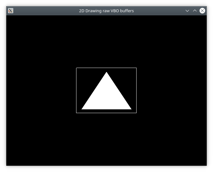
Source Code
- This CMakeLists.txt building script saves the user from manually downloading, building, installing and configuring OpenGL Glew and GLFW companion libraries. This file automatically downloads the GLFW library, that provides window system abstraction and OpenGL context; and a pre-compiled GLEW library (Windows only) that provides platform-agnostic OpenGL function pointer loading.
- The CMakeLists.txt (version 2) contains a macro for defining OpenGL applications without the boilerplate needed for linking against OpenGL companion libraries and statically linking against MINGW runtimme libraries.
File: CMakeLists.txt (Version 1)
cmake_minimum_required(VERSION 3.5)
project(OpenGL_Draw2D_VBO)

set(CMAKE_CXX_STANDARD 17)
set(CMAKE_CXX_STANDARD_REQUIRED ON)
set(CMAKE_VERBOSE_MAKEFILE ON)

#================ GLFW Settings  ===============#

find_package(OpenGL REQUIRED)

include(FetchContent)

# Set GLFW Options before FectchContent_MakeAvailable
set( GLFW_BUILD_EXAMPLES OFF CACHE BOOL  "GLFW lib only" )
set( GLFW_BUILD_TESTS    OFF CACHE BOOL  "GLFW lib only" )
set( GLFW_BUILD_DOCS     OFF CACHE BOOL  "GLFW lib only" )
set( GLFW_BUILD_INSTALL  OFF CACHE BOOL  "GLFW lib only" )

# Donwload GLFW library
FetchContent_Declare(
  glfwlib
  URL   https://github.com/glfw/glfw/releases/download/3.3.2/glfw-3.3.2.zip
)
FetchContent_MakeAvailable(glfwlib)

# Download pre-compiled GLEW when building under Windows NT OS (x64)
IF(WIN32)
   FetchContent_Declare(
      glew-release
      URL  https://ufpr.dl.sourceforge.net/project/glew/glew/2.1.0/glew-2.1.0-win32.zip
      # No longer valid URL
      ## URL     https://megalink.dl.sourceforge.net/project/glew/glew/2.1.0/glew-2.1.0-win32.zip
   )
   FetchContent_MakeAvailable(glew-release)
   include_directories( ${glew-release_SOURCE_DIR}/include  ${glm_SOURCE_DIR} )
   link_directories(  ${glew-release_SOURCE_DIR}/lib/Release/x64 )

   set( GLEW_LIB_PATH1 ${glew-release_SOURCE_DIR}/lib/Release/x64/glew32.lib )
   set( GLEW_LIB_PATH2 ${glew-release_SOURCE_DIR}/lib/Release/x64/glew32s.lib )
ENDIF()

   # ======= T A R G E T S ============================#
   #                                                   #


       add_executable( draw2d-raw  draw2d-raw.cpp )
target_link_libraries( draw2d-raw  glfw
                                   OpenGL::GL
                                   ${GLEW_LIB_PATH1} ${GLEW_LIB_PATH2}  )

# For MINGW (GCC Ported to Windows)
IF(MINGW)
   # Statically link against MINGW dependencies
   # for making easier to deploy on other machines.
   target_link_options( draw2d-raw PRIVATE
                            -static-libgcc
                            -static-libstdc++

                            -Wl,-Bstatic,--whole-archive -lwinpthread
                              -Wl,--no-whole-archive
                            )
ENDIF()


# Copy GLEW DLL shared library to same directory as the executable.
IF(WIN32)
   add_custom_command(TARGET draw2d-raw POST_BUILD
                  COMMAND ${CMAKE_COMMAND} -E copy_if_different
                  "${glew-release_SOURCE_DIR}/bin/Release/x64/glew32.dll"
                  $<TARGET_FILE_DIR:draw2d-raw>)
ENDIF()
File: CMakeLists.txt (Version 2) - This version provides a macro for automating the definition of OpenGL projects with ADD_OPENGL command.
cmake_minimum_required(VERSION 3.5)
project(OpenGL_Draw2D_VBO)

set(CMAKE_CXX_STANDARD 17)
set(CMAKE_CXX_STANDARD_REQUIRED ON)
set(CMAKE_VERBOSE_MAKEFILE ON)

#================ GLFW Settings  ===============#

find_package(OpenGL REQUIRED)

include(FetchContent)

# Set GLFW Options before FectchContent_MakeAvailable
set( GLFW_BUILD_EXAMPLES OFF CACHE BOOL  "GLFW lib only" )
set( GLFW_BUILD_TESTS    OFF CACHE BOOL  "GLFW lib only" )
set( GLFW_BUILD_DOCS     OFF CACHE BOOL  "GLFW lib only" )
set( GLFW_BUILD_INSTALL  OFF CACHE BOOL  "GLFW lib only" )

# Donwload GLFW library
FetchContent_Declare(
  glfwlib
  URL   https://github.com/glfw/glfw/releases/download/3.3.2/glfw-3.3.2.zip
)
FetchContent_MakeAvailable(glfwlib)

# Download pre-compiled GLEW when building under Windows NT OS (x64)
IF(WIN32)
   FetchContent_Declare(
      glew-release
      URL  https://ufpr.dl.sourceforge.net/project/glew/glew/2.1.0/glew-2.1.0-win32.zip
      # https://github.com/nigels-com/glew/archive/glew-2.2.0.zip
   )
   FetchContent_MakeAvailable(glew-release)
   include_directories( ${glew-release_SOURCE_DIR}/include  ${glm_SOURCE_DIR} )
   link_directories(  ${glew-release_SOURCE_DIR}/lib/Release/x64 )

   set( GLEW_LIB_PATH1 ${glew-release_SOURCE_DIR}/lib/Release/x64/glew32.lib )
   set( GLEW_LIB_PATH2 ${glew-release_SOURCE_DIR}/lib/Release/x64/glew32s.lib )
ENDIF()


MACRO(ADD_OPENGL_APP target sources)
   add_executable( ${target} ${sources} )
   message([TRACE] " Add OpenGL executable = ${target} ")

   target_link_libraries( ${target} glfw
                                    OpenGL::GL
                                    ${GLEW_LIB_PATH1}
                                    ${GLEW_LIB_PATH2} )

    IF(MINGW)
        # Statically link against MINGW dependencies
        # for making easier to deploy on other machines.
        target_link_options( ${target} PRIVATE
                                 -static-libgcc
                                 -static-libstdc++
                                 -Wl,-Bstatic,--whole-archive -lwinpthread
                                   -Wl,--no-whole-archive
                                 )
     ENDIF()


     # Copy GLEW DLL shared library to same directory as the executable.
     IF(WIN32)
        add_custom_command(TARGET ${target} POST_BUILD
                       COMMAND ${CMAKE_COMMAND} -E copy_if_different
                       "${glew-release_SOURCE_DIR}/bin/Release/x64/glew32.dll"
                       $<TARGET_FILE_DIR:${target}>)
     ENDIF()
ENDMACRO()

     # ======= T A R G E T S ============================#
     #                                                   #

ADD_OPENGL_APP( draw2-raw draw2d-raw.cpp )
File: CMakeLists.txt (Version 3) - last resort if the SourceForge link no longer works. In this case, it is assumed that Glew library was download manually from SourceForge via the URL (glew-2.1.0 - download). Then the ZIP glew-2.1.0-win32.zip is saved in the project root directory and extracted to a directory named ./glew-2.1.0/
# Used when Glew library is download manually
cmake_minimum_required(VERSION 3.5)
project(OpenGL_Draw2D_VBO)

set(CMAKE_CXX_STANDARD 17)
set(CMAKE_CXX_STANDARD_REQUIRED ON)
set(CMAKE_VERBOSE_MAKEFILE ON)

#================ GLFW Settings  ===============#

find_package(OpenGL REQUIRED)

include(FetchContent)

# Set GLFW Options before FectchContent_MakeAvailable
set( GLFW_BUILD_EXAMPLES OFF CACHE BOOL  "GLFW lib only" )
set( GLFW_BUILD_TESTS    OFF CACHE BOOL  "GLFW lib only" )
set( GLFW_BUILD_DOCS     OFF CACHE BOOL  "GLFW lib only" )
set( GLFW_BUILD_INSTALL  OFF CACHE BOOL  "GLFW lib only" )

# Donwload GLFW library
FetchContent_Declare(
  glfwlib
  URL   https://github.com/glfw/glfw/releases/download/3.3.2/glfw-3.3.2.zip
)
FetchContent_MakeAvailable(glfwlib)

# Download pre-compiled GLEW when building under Windows NT OS (x64)
IF(WIN32)
   include_directories( ${CMAKE_CURRENT_LIST_DIR}/glew-2.1.0/include  ${glm_SOURCE_DIR} )
   link_directories(  ${CMAKE_CURRENT_LIST_DIR}/glew-2.1.0/lib/Release/x64 )

   set( GLEW_LIB_PATH1  ${CMAKE_CURRENT_LIST_DIR}/glew-2.1.0/lib/Release/x64/glew32.lib )
   set( GLEW_LIB_PATH2  ${CMAKE_CURRENT_LIST_DIR}/glew-2.1.0/lib/Release/x64/glew32s.lib )
ENDIF()

   # ======= T A R G E T S ============================#
   #                                                   #

       add_executable( draw2d-raw  draw2d-raw.cpp )
target_link_libraries( draw2d-raw  glfw
                                   OpenGL::GL
                                   ${GLEW_LIB_PATH1} ${GLEW_LIB_PATH2}  )

# For MINGW (GCC Ported to Windows)
IF(MINGW)
   # Statically link against MINGW dependencies
   # for making easier to deploy on other machines.
   target_link_options( draw2d-raw PRIVATE
                            -static-libgcc
                            -static-libstdc++

                            -Wl,-Bstatic,--whole-archive -lwinpthread
                              -Wl,--no-whole-archive
                            )
ENDIF()


# Copy GLEW DLL shared library to same directory as the executable.
IF(WIN32)
   add_custom_command(TARGET draw2d-raw POST_BUILD
                  COMMAND ${CMAKE_COMMAND} -E copy_if_different
                  "${CMAKE_CURRENT_LIST_DIR}/glew-2.1.0/bin/Release/x64/glew32.dll"
                  $<TARGET_FILE_DIR:draw2d-raw>)
ENDIF()
Downloading glew manually with curl for usage with the previous CMakeLists.txt file:
 $ curl -L -o glew32.zip  https://ufpr.dl.sourceforge.net/project/glew/glew/2.1.0/glew-2.1.0-win32.zip

 # File hash (file signature) - unique identifier for the file
 $ md5sum glew32.zip
 32a72e6b43367db8dbea6010cd095355  glew32.zip

 # File hash (file signature) - unique identifier for the file
 $ sha256sum glew32.zip
 80cfc88fd295426b49001a9dc521da793f8547ac10aebfc8bdc91ddc06c5566c  glew32.zip

 # File hash (file signature) - unique identifier for the file
 $ sha1sum glew32.zip
 f505a67ad884b75648639a9b01bf0245bfcfa731  glew32.zip

$ unzip -l glew32.zip
 Archive:  glew32.zip
   Length      Date    Time    Name
 ---------  ---------- -----   ----
         0  2017-07-31 08:46   glew-2.1.0/
         0  2017-07-31 08:41   glew-2.1.0/bin/
         0  2017-07-31 08:42   glew-2.1.0/bin/Release/
         0  2017-07-31 08:42   glew-2.1.0/bin/Release/Win32/
    389632  2017-07-31 08:42   glew-2.1.0/bin/Release/Win32/glew32.dll
    482304  2017-07-31 08:42   glew-2.1.0/bin/Release/Win32/glewinfo.exe
    294912  2017-07-31 08:42   glew-2.1.0/bin/Release/Win32/visualinfo.exe
         0  2017-07-31 08:42   glew-2.1.0/bin/Release/x64/
    422912  2017-07-31 08:42   glew-2.1.0/bin/Release/x64/glew32.dll
    539648  2017-07-31 08:42   glew-2.1.0/bin/Release/x64/glewinfo.exe
    338432  2017-07-31 08:42   glew-2.1.0/bin/Release/x64/visualinfo.exe
    ... ... ... ... ... ... ... ... ... ... ... ... ... ... ..
    ... ... ... ... ... ... ... ... ... ... ... ... ... ... ..

         0  2017-07-31 08:42   glew-2.1.0/lib/Release/
         0  2017-07-31 08:46   glew-2.1.0/lib/Release/Win32/
    712098  2017-07-31 08:42   glew-2.1.0/lib/Release/Win32/glew32.lib
   2443636  2017-07-31 08:42   glew-2.1.0/lib/Release/Win32/glew32s.lib
         0  2017-07-31 08:46   glew-2.1.0/lib/Release/x64/
    701288  2017-07-31 08:42   glew-2.1.0/lib/Release/x64/glew32.lib
   2584968  2017-07-31 08:42   glew-2.1.0/lib/Release/x64/glew32s.lib
      3870  2017-07-31 08:46   glew-2.1.0/LICENSE.txt
 ---------                     -------
  10662952                     47 files

 $ unzip -x glew32.zip
 Archive:  glew32.zip
    creating: glew-2.1.0/
    creating: glew-2.1.0/bin/
    creating: glew-2.1.0/bin/Release/
    creating: glew-2.1.0/bin/Release/Win32/
   inflating: glew-2.1.0/bin/Release/Win32/glew32.dll
   inflating: glew-2.1.0/bin/Release/Win32/glewinfo.exe
  ... ... ... ... ... ... ... ... ... ... ... ... ... ...
  ... ... ... ... ... ... ... ... ... ... ... ... ... ...
    inflating: glew-2.1.0/lib/Release/Win32/glew32.lib
   inflating: glew-2.1.0/lib/Release/Win32/glew32s.lib
    creating: glew-2.1.0/lib/Release/x64/
   inflating: glew-2.1.0/lib/Release/x64/glew32.lib
   inflating: glew-2.1.0/lib/Release/x64/glew32s.lib
   inflating: glew-2.1.0/LICENSE.txt
File: xmake.lua
- Compilation script for Xmake building system, that uses Lua as embedded scripting language and as a DSL - Domain-Specific Language. The disadvantage of this building system are: poor IDE support and the lack of ability for downloading sources directly like CMake's FetchContent_Declare statement. Another issue is that new packages can only be added by sending pull requests to Xmake packages repository.
- XMake packages used in this sample project:
add_rules("mode.debug", "mode.release")

add_requires("glm", "glew", "glfw")

target("draw2d")
  set_kind("binary")
  add_files("./draw2d-raw.cpp")
  add_packages("glew", "glfw", "glm")
File: draw2d-raw.cpp
#include <iostream>
#include <vector>
#include <array>
#include <cmath>
#include <cassert>

// -------- OpenGL headers ---------//
//
#define GL_GLEXT_PROTOTYPES 1 // Necessary for OpenGL >= 3.0 functions
#define GL3_PROTOTYPES      1 // Necessary for OpenGL >= 3.0 functions


#if defined(_WIN32)
   #include <windows.h>
   #include <GL/glew.h>
#endif

#include <GL/gl.h>
#include <GLFW/glfw3.h>

#include <GL/glu.h>
// #include <GL/glut.h>


struct Vertex2D
{
    GLfloat x;
    GLfloat y;
};

int main(int argc, char** argv)
{
    GLFWwindow* window;

    // Initialize GLFW
    if (!glfwInit()){ return -1; }


    /* Create a windowed mode window and its OpenGL context */
    window = glfwCreateWindow(640, 480, "2D Drawing raw VBO buffers", NULL, NULL);
    if (!window)
    {
        glfwTerminate();
        return -1;
    }

    /* Make the window's context current */
    glfwMakeContextCurrent(window);
    // glClearColor(0.0f, 0.5f, 0.6f, 1.0f);
    glClearColor(0.0f, 0.0f, 0.0, 1.0f);

    // --- GLEW should always be initialized after an OpenGL context.
    #if _WIN32
    glewExperimental = GL_TRUE;
    if (glewInit() != GLEW_OK) {
        std::cerr << "GLEW::Error : failed to initialize GLEW"<< std::endl;
    }
    std::fprintf(stderr, " [TRACE] Glew Initialized Ok. \n");
    #endif


    Vertex2D triangle_points[3] = {
        Vertex2D{-0.25,   -0.25}
      , Vertex2D{ 0.00,   0.25}
      , Vertex2D{ 0.25,  -0.25}
    };

    Vertex2D square_points[4] = {
        { -0.3,  -0.3 }
      , { -0.3,   0.3 }
      , {  0.3,   0.3 }
      , {  0.3,  -0.3 }
    };

    // ================== Triangle Buffer ====================//
    //

    GLuint vbo_triangle_ = 0;

    // Create an OpenGL VBO buffer
    // =>> void glGenBuffers (GLsizei n, GLuint *buffers);
    glGenBuffers(  1                // Number of buffers that will be instantiated
                 , &vbo_triangle_   // Address of first element or address of array
                                    // that results will be written to.
                 );
    assert( vbo_triangle_ != 0 );

    // Set this buffer as the current buffer - Only one buffer can be bound at a time.
    // =>> void glBindBuffer (GLenum target, GLuint buffer)
    glBindBuffer(GL_ARRAY_BUFFER, vbo_triangle_);

    // Upload data to current VBO buffer in GPU
    glBufferData(GL_ARRAY_BUFFER, sizeof(triangle_points), triangle_points, GL_STATIC_DRAW);

    // Unbind current buffer in order to avoid unintended behaviors
    // as the subroutine glBindBuffer() modifies has a global state.
    glBindBuffer(GL_ARRAY_BUFFER, 0);

    // ================ Square / Vertex Buffer Object 2 ==================//
    //

    GLuint vbo_square_ = 0;
    // Instiate buffer - gets a handle or token for
    // a buffer allocated on GPU-side.
    glGenBuffers(1, &vbo_square_);
    // Check for error
    assert( vbo_square_ != 0);
    // Bind Current buffer (Affects global state)
    glBindBuffer(GL_ARRAY_BUFFER, vbo_square_);
    // Upload data to the GPU
    glBufferData(GL_ARRAY_BUFFER, sizeof(square_points), square_points, GL_STATIC_DRAW);
    // Unbind buffer
    glBindBuffer(GL_ARRAY_BUFFER, 0);

    GLint shader_attr = 0;

    //  ======= R E N D E R  - L O O P ============//
    //
    while ( !glfwWindowShouldClose(window) )
    {
        glClear(GL_COLOR_BUFFER_BIT);

        // ====== BEGIN RENDERING ============//

            // ------------ Draw triangle --------------//
            //
            glBindBuffer(GL_ARRAY_BUFFER, vbo_triangle_);
            glEnableVertexAttribArray(shader_attr);

            // Describe buffer data layout (binary layout)
            // =>> glVertexAttribPointer ( GLuint index, GLint size, GLenum type
            //                           , GLboolean normalized, GLsizei stride, const void *pointer);
            //
            glVertexAttribPointer(shader_attr // GLint  index         => Shader attribute location, 0 for now
                                , 2           // GLint  size          => 2 components (X, Y) of type GLfloat
                                , GL_FLOAT    // GLemum type          => Type of each component
                                , GL_FALSE    // GLboolean normalized
                                , 0           // GLsizei stride
                                , nullptr     // const void* pointer
                                );
            // Draw arrays using the content of buffer
            // Plot 1 triangle (each triangle has 3 vertices)
            glDrawArrays(GL_TRIANGLES, 0, 3);

            // Disable global state
            glBindBuffer(GL_ARRAY_BUFFER, 0);
            glDisableVertexAttribArray(0);

            //------------ Draw Square -------------------------//
            //

            #if 1
            glBindBuffer(GL_ARRAY_BUFFER, vbo_square_);
            glEnableVertexAttribArray(shader_attr);
            glVertexAttribPointer(0, 2, GL_FLOAT, GL_FALSE, 0, nullptr);
            // Plot 4 vertices
            glDrawArrays(GL_LINE_LOOP, 0, 4);

            // Disable global state
            glBindBuffer(GL_ARRAY_BUFFER, 0);
            glDisableVertexAttribArray(shader_attr);
            #endif

        // ====== END RENDERING ==============//

        /* Swap front and back buffers */
        glfwSwapBuffers(window);
        /* Poll for and process events */
        glfwPollEvents();

        if( glfwGetKey(window, 'Q' ) == GLFW_PRESS )
        {
             std::cout << " [TRACE] User typed Q =>> Shutdown program. Ok. " << '\n';
             break;
        }
    }

    glfwTerminate();
    return 0;
}
Building on Linux
$ cmake -H. -B_build_linux -DCMAKE_BUILD_TYPE=Debug
$ cmake --build _build_linux --target

# Run
$ _build_linux/draw2d-raw
Building with dockercross tool (cross compilation for Windows)
- See: Cross compiling toolchains in Docker images
$ docker run -it --rm -v $PWD:/cwd -w /cwd --entrypoint=bash dockcross/windows-static-x64

$ cmake -H. -B_build_cross -DCMAKE_BUILD_TYPE=Debug
$ cmake --build _build_cross --target
Building without entering docker shell:
$ docker run -it --rm -v $PWD:/cwd -w /cwd --entrypoint=bash dockcross/windows-static-x64 cmake -H. -B_build_cross -DCMAKE_BUILD_TYPE=Debug
$ docker run -it --rm -v $PWD:/cwd -w /cwd --entrypoint=bash dockcross/windows-static-x64 cmake --build _build_cross --target
List build directory:
$ ls _build_cross
CMakeCache.txt CMakeFiles  Makefile  _deps  cmake_install.cmake  draw2d-raw.exe  glew32.dll
Run executable with wine on Linux:
$ wine _build_cross/draw2d-raw.exe
Building on Windows with MINGW (GCC ported to Windows)
$ cmake -H. -B_build_mingw -G "MinGW Makefiles" -DCMAKE_BUILD_TYPE=Debug
$ cmake --build _build_mingw --target
Run executable:
# On Window
$ _build_mingw\draw2d-raw.exe

# on Linux via wine
$ wine _build_mingw\draw2d-raw.exe
Building with Xmake building system
Display Xmake version:
$ xmake --version | grep -i "cross-platform" 2> /dev/null
xmake v2.6.9+202208081520, A cross-platform build utility based on Lua
Enter XMake - Lua interactive REPL (Read-Eval-Print-Loop):
$ xmake lua
xmake>

xmake> -- Get host operating system
xmake> os.host()
< "linux"

xmake> -- Get host architecture
xmake> os.arch()
< "x86_64"

xmake> -- Open Root Linux's directory
xmake> os.execv("xdg-open /")
< 1: 0
< 2: nil

xmake> -- Check whether file exists
xmake> os.exists("./draw2d-raw.cpp")
< true
xmake> os.exists("./draw2d-raw.cpp.back")
< false

xmake> -- Get current directory
xmake> os.curdir()
< "/home/user/opengl1"

xmake> -- Get project directory
xmake> os.projectdir()
< "/home/user/opengl1"

xmake> -- Get scripting directory
xmake> os.scriptdir()
< "/home/user/.local/share/xmake/plugins/lua"

xmake> -- Download file from http server
xmake> http = import("net.http")
xmake> http.download("https://github.com/glfw/glfw/releases/download/3.3.2/glfw-3.3.2.zip", "glfw-source.zip")
xmake> os.exists("glfw-source.zip")
< true

xmake> -- Extract archive
xmake> r = import("utils.archive")
xmake> r.extract("./glfw-source.zip", "/tmp/glfw-src")


-- Check current platform (All return false in the REPL)
xmake> is_plat("windows")
< false
xmake> is_plat("linux")
< false
xmake> is_plat("unix")
< false

xmake> -- Check whether the current mode is Debug or Release (All fail in the REPL)
xmake> is_mode("debug")
< false
xmake> is_mode("release")
< false

xmake> -- Join paths
xmake> p = path.join( os.projectdir(), "build", "path1", "path2", "app.exe")
xmake> p
< "/home/user/opengl1/build/path1/path2/app.exe"


-- Environment variable
xmake> os.getenv("HOME")
< "/home/user"

xmake> os.getenv("SHELL")
< "/bin/bash"

xmake> os.getenv("TERM")
< "xterm-256color"
List repositories:
- $ xrepo list-repo
$ xrepo list-repo
global repositories:
    build-artifacts https://gitlab.com/xmake-mirror/build-artifacts.git main
    xmake-repo https://gitlab.com/tboox/xmake-repo.git master
    builtin-repo /home/user/.local/share/xmake/repository

3 repositories were found!
Search Xmake packages:
- $ xrepo search <PACKAGE>
$ xrepo search boost
The package names:
    boost:
      -> boost-1.79.0: Collection of portable C++ source libraries. (in xmake-repo)

$ xrepo search glut
The package names:
    glut:
      -> freeglut-3.2.2: A free-software/open-source alternative to the OpenGL Utility Toolkit (GLUT) library. (in xmake-repo)
      -> glut: OpenGL utility toolkit (in xmake-repo)
Install package:
- $ xrepo install <PACKAGE>
 $ xrepo install boost

note: install or modify (m) these packages (pass -y to skip confirm)?
in xmake-repo:
  -> bzip2 1.0.8 [from:boost]
  -> boost 1.79.0
please input: y (y/n/m)
y
  => download https://sourceware.org/pub/bzip2/bzip2-1.0.8.tar.gz .. ok
List package information:
- $ xrepo info <PACKAGE>
 $ >> xrepo info glm
The package info of project:
    require(glm):
      -> description: OpenGL Mathematics (GLM)
      -> version: 0.9.9+8
      -> urls:
         -> https://github.com/g-truc/glm/archive/0.9.9.8.tar.gz
            -> 7d508ab72cb5d43227a3711420f06ff99b0a0cb63ee2f93631b162bfe1fe9592
         -> https://github.com/g-truc/glm.git
            -> 0.9.9+8
      -> repo: xmake-repo https://gitlab.com/tboox/xmake-repo.git master
      -> cachedir: /home/user/.xmake/cache/packages/2208/g/glm/0.9.9+8
      -> installdir: /home/user/.xmake/packages/g/glm/0.9.9+8/65b1ad153bda4a43b0454eba7969327f
      -> searchdirs:
      -> searchnames: 0.9.9.8.tar.gz, glm.git, glm-0.9.9+8.tar.gz, glm-0.9.9+8
      -> fetchinfo: 0.9.9+8
          -> sysincludedirs: /home/user/.xmake/packages/g/glm/0.9.9+8/65b1ad153bda4a43b0454eba7969327f/include
          -> version: 0.9.9+8
      -> platforms: all
      -> requires:
         -> plat: linux
         -> arch: x86_64
         -> configs:
            -> debug: false
            -> pic: true
            -> shared: false
      -> configs:
      -> configs (builtin):
         -> debug: Enable debug symbols. (default: false)
         -> shared: Build shared library. (default: false)
         -> pic: Enable the position independent code. (default: true)
         -> lto: Enable the link-time build optimization. (type: boolean)
         -> vs_runtime: Set vs compiler runtime.
            -> values: {"MT","MTd","MD","MDd"}
         -> toolchains: Set package toolchains only for cross-compilation.
         -> cflags: Set the C compiler flags.
         -> cxflags: Set the C/C++ compiler flags.
         -> cxxflags: Set the C++ compiler flags.
         -> asflags: Set the assembler flags.
      -> references:
         -> 220814: /dev/shm/.xmake1000/220814/xrepo/working
         -> 220813: /home/user/opengl1
List project information:
- $ xmake show
$ xmake show

The information of xmake:
    version: 2.6.9+202208081520
    host: linux/x86_64
    programdir: /home/user/.local/share/xmake
    programfile: /home/user/.local/bin/xmake
    globaldir: /home/user/.xmake
    tmpdir: /dev/shm/.xmake1000/220808
    workingdir: /home/user/opengl1
    packagedir: /home/user/.xmake/packages
    packagedir(cache): /home/user/.xmake/cache/packages/2208

The information of project:
    plat: linux
    arch: x86_64
    mode: release
    buildir: build
    configdir: /home/user/opengl1/.xmake/linux/x86_64
    projectdir: /home/user/opengl1
    projectfile: /home/user/opengl1/xmake.lua
Configure building for Linux:
- $ xmake f -p linux
 $ >> xmake f -p linux
checking for architecture ... x86_64
Building:
- $ xmake build
 $ >> xmake build -v
[ 25%]: ccache compiling.release draw2d-raw.cpp
/usr/bin/gcc -c -m64 -fvisibility=hidden -fvisibility-inlines-hidden -O3 -DGLEW_NO_GLU -D_GLFW_X11 -DGLFW_INCLUDE_NONE \
               -isystem /home/user/.xmake/packages/g/glew/2.2.0/2ac0c6940a2140f7b6506fcd8240f406/include \
               -isystem /home/user/.xmake/packages/g/glfw/3.3.8/aa037e96cc854680a09e144c4b5c8fe0/include \
               -isystem /usr/include/X11/dri -isystem /home/user/.xmake/packages/g/glm/0.9.9+8/65b1ad153bda4a43b0454eba7969327f/include \
               -DNDEBUG -o build/.objs/draw2d/linux/x86_64/release/draw2d-raw.cpp.o draw2d-raw.cpp

[ 50%]: linking.release draw2d
/usr/bin/g++ -o build/linux/x86_64/release/draw2d build/.objs/draw2d/linux/x86_64/release/draw2d-raw.cpp.o -m64 \
               -L/home/user/.xmake/packages/g/glew/2.2.0/2ac0c6940a2140f7b6506fcd8240f406/lib \
               -L/home/user/.xmake/packages/g/glfw/3.3.8/aa037e96cc854680a09e144c4b5c8fe0/lib \
                -L/usr/lib/x86_64-linux-gnu -s \
                -lglew -lglfw3 -lOpenGL -lXrandr -lXinerama -lXcursor -lXrender -lX11 -lXi -lXfixes \
                -lXext -lxcb -lssl -lcrypto -lffi -lz -lXau -lXdmcp -lGL -ldl -lpthread
[100%]: build ok!
Inspecting compilation output:
$ tree build
build
└── linux
    └── x86_64
        └── release
            └── draw2d

3 directories, 1 file
Running the default xmake target:
- $ xmake run
$ xmake run
Running a specific xmake target:
- $ xmake run draw2d
$ xmake run draw2d
Generate file containing compilation commands:
$ xmake project -k compile_commands
create ok!

$ cat compile_commands.json
[
{
  "directory": "/home/user/opengl1",
  "arguments": ["/usr/bin/gcc", "-c", "-m64", "-fvisibility=hidden", "-fvisibility-inlines-hidden", "-O3", "-DGLEW_NO_GLU", "-D_GLFW_X11", "-DGLFW_INCLUDE_NONE", "-I", "/home/user/.xmake/packages/g/glew/2.2.0/2ac0c6940a2140f7b6506fcd8240f406/include", "-I", "/home/user/.xmake/packages/g/glfw/3.3.8/aa037e96cc854680a09e144c4b5c8fe0/include", "-I", "/usr/include/X11/dri", "-I", "/home/user/.xmake/packages/g/glm/0.9.9+8/65b1ad153bda4a43b0454eba7969327f/include", "-DNDEBUG", "-o", "build/.objs/draw2d/linux/x86_64/release/draw2d-raw.cpp.o", "draw2d-raw.cpp"],
  "file": "draw2d-raw.cpp"
}]
Generate a CMake project file (note - this file must not be under version control):
- $ xmake project -k cmake
$ xmake project -k cmake
create ok!
CMake file generated by Xmake (CMakeLists.txt):
# this is the build file for project
# it is autogenerated by the xmake build system.
# do not edit by hand.

# project
cmake_minimum_required(VERSION 3.15.0)
cmake_policy(SET CMP0091 NEW)
project(draw2d LANGUAGES CXX C)

# target
add_executable(draw2d "")
set_target_properties(draw2d PROPERTIES OUTPUT_NAME "draw2d")
set_target_properties(draw2d PROPERTIES RUNTIME_OUTPUT_DIRECTORY "${CMAKE_SOURCE_DIR}/build/linux/x86_64/release")
target_include_directories(draw2d PRIVATE
    /home/user/.xmake/packages/g/glew/2.2.0/2ac0c6940a2140f7b6506fcd8240f406/include
    /usr/include/X11/dri
    /home/user/.xmake/packages/g/glfw/3.3.6/703496809fe34548a9dbcf268bfa4db5/include
    /home/user/.xmake/packages/g/glm/0.9.9+8/65b1ad153bda4a43b0454eba7969327f/include
)
target_compile_definitions(draw2d PRIVATE
    GLEW_NO_GLU
    _GLFW_X11
    GLFW_INCLUDE_NONE
)
target_compile_options(draw2d PRIVATE
    $<$<COMPILE_LANGUAGE:C>:-m64>
    $<$<COMPILE_LANGUAGE:CXX>:-m64>
    $<$<COMPILE_LANGUAGE:C>:-DNDEBUG>
    $<$<COMPILE_LANGUAGE:CXX>:-DNDEBUG>
)
if(MSVC)
    target_compile_options(draw2d PRIVATE $<$<CONFIG:Release>:-Ox -fp:fast>)
else()
    target_compile_options(draw2d PRIVATE -O3)
endif()
if(MSVC)
else()
    target_compile_options(draw2d PRIVATE -fvisibility=hidden)
endif()
if(MSVC)
    set_property(TARGET draw2d PROPERTY
        MSVC_RUNTIME_LIBRARY "MultiThreaded$<$<CONFIG:Debug>:Debug>")
endif()
target_link_libraries(draw2d PRIVATE
    glew
    X11
    xcb
    ssl
    crypto
    ffi
    z
    Xau
    Xdmcp
    glfw3
    OpenGL
    Xrandr
    Xinerama
    Xcursor
    Xrender
    Xi
    Xfixes
    Xext
    GL
    dl
    pthread
)
target_link_directories(draw2d PRIVATE
    /home/user/.xmake/packages/g/glew/2.2.0/2ac0c6940a2140f7b6506fcd8240f406/lib
    /usr/lib/x86_64-linux-gnu
    /home/user/.xmake/packages/g/glfw/3.3.6/703496809fe34548a9dbcf268bfa4db5/lib
)
target_link_options(draw2d PRIVATE
    -m64
)
target_sources(draw2d PRIVATE
    draw2d-raw.cpp
)
Now it is possible to edit the project with any IDE or smart editor that supports CMake, including Visual Studio Code - Vscode or CLion:
# Edit project with vscode using the CMakeLists.txt as project file
$ vscode .
Building with Xmake building system on Windows
Configure XMake for using MinGW (GCC Ported to Windows)
$ xmake f -p mingw
Show project information:
$ xmake show

The information of xmake:
    version: 2.7.1+master.1acf248c0
    host: windows/x64
    programdir: C:\Program Files\xmake
    programfile: C:\Program Files\xmake\xmake.exe
    globaldir: C:\Users\ghostuser\AppData\Local\.xmake
    tmpdir: C:\Users\ghostuser\AppData\Local\Temp\.xmake\220902
    workingdir: D:\opengl
    packagedir: C:\Users\ghostuser\AppData\Local\.xmake\packages
    packagedir(cache): C:\Users\ghostuser\AppData\Local\.xmake\cache\packages\2209

The information of project:
    plat: mingw
    arch: x86_64
    mode: release
    buildir: build
    configdir: D:\opengl\.xmake\windows\x64
    projectdir: D:\opengl
    projectfile: D:\opengl\xmake.lua
Build the application showing all compilation and linking commands:
$ xmake build -v

[ 25%]: cache compiling.release draw2d-raw.cpp
"C:\\Program Files\\mingw-w64\\x86_64-8.1.0-posix-seh-rt_v6-rev0\\mingw64\\bin\\x86_64-w64-mingw32-g++" -c \
    -m64 -fvisibility=hidden -fvisibility-inlines-hidden -O3 -DGLEW_NO_GLU -DGLEW_STATIC -DGLFW_INCLUDE_NONE \
    -isystem C:\Users\ghostuser\AppData\Local\.xmake\packages\g\glew\2.2.0\f1937cf4c620461cac69417973f0b9e2\include \
    -isystem C:\Users\ghostuser\AppData\Local\.xmake\packages\g\glfw\3.3.8\580b60fd05d941e2abb98f9baa25683e\include \
    -isystem C:\Users\ghostuser\AppData\Local\.xmake\packages\g\glm\0.9.9+8\53c948164ca94a25beb29600f690b730\include -DNDEBUG \
    -o build\.objs\draw2d\mingw\x86_64\release\draw2d-raw.cpp.obj draw2d-raw.cpp

[ 50%]: linking.release draw2d.exe
"C:\\Program Files\\mingw-w64\\x86_64-8.1.0-posix-seh-rt_v6-rev0\\mingw64\\bin\\x86_64-w64-mingw32-g++" \
    -o build\mingw\x86_64\release\draw2d.exe build\.objs\draw2d\mingw\x86_64\release\draw2d-raw.cpp.obj -m64 \
    -LC:\Users\ghostuser\AppData\Local\.xmake\packages\g\glew\2.2.0\f1937cf4c620461cac69417973f0b9e2\lib \
    -LC:\Users\ghostuser\AppData\Local\.xmake\packages\g\glfw\3.3.8\580b60fd05d941e2abb98f9baa25683e\lib \
    -s -lglew32s -lglfw3 -lopengl32 -lgdi32
[100%]: build ok!
Run the executable:
$ xmake run
Generate CMakeLists.txt:
$ xmake project -k cmake
Build the project using the CMakeListst.txt file:
$ cmake -H. -B_build -G "MinGW Makefiles" -DCMAKE_BUILD_TYPE=Debug

$ cmake --build _build --target all
[ 50%] Building CXX object CMakeFiles/draw2d.dir/draw2d-raw.cpp.obj
[100%] Linking CXX executable ..\build\mingw\x86_64\release\draw2d.exe
[100%] Built target draw2d
File: CMakeLists.txt - generated by XMake
# this is the build file for project
# it is autogenerated by the xmake build system.
# do not edit by hand.

# project
cmake_minimum_required(VERSION 3.15.0)
cmake_policy(SET CMP0091 NEW)
project(draw2d LANGUAGES CXX C)

# target
add_executable(draw2d "")
set_target_properties(draw2d PROPERTIES OUTPUT_NAME "draw2d")
set_target_properties(draw2d PROPERTIES RUNTIME_OUTPUT_DIRECTORY "${CMAKE_SOURCE_DIR}/build/mingw/x86_64/release")
target_include_directories(draw2d PRIVATE
    C:/Users/ghostuser/AppData/Local/.xmake/packages/g/glew/2.2.0/f1937cf4c620461cac69417973f0b9e2/include
    C:/Users/ghostuser/AppData/Local/.xmake/packages/g/glfw/3.3.8/580b60fd05d941e2abb98f9baa25683e/include
    C:/Users/ghostuser/AppData/Local/.xmake/packages/g/glm/0.9.9+8/53c948164ca94a25beb29600f690b730/include
)
target_compile_definitions(draw2d PRIVATE
    GLEW_NO_GLU
    GLEW_STATIC
    GLFW_INCLUDE_NONE
)
target_compile_options(draw2d PRIVATE
    $<$<COMPILE_LANGUAGE:C>:-m64>
    $<$<COMPILE_LANGUAGE:CXX>:-m64>
    $<$<COMPILE_LANGUAGE:C>:-DNDEBUG>
    $<$<COMPILE_LANGUAGE:CXX>:-DNDEBUG>
)
if(MSVC)
    target_compile_options(draw2d PRIVATE $<$<CONFIG:Release>:-Ox -fp:fast>)
else()
    target_compile_options(draw2d PRIVATE -O3)
endif()
if(MSVC)
else()
    target_compile_options(draw2d PRIVATE -fvisibility=hidden)
endif()
if(MSVC)
    set_property(TARGET draw2d PROPERTY
        MSVC_RUNTIME_LIBRARY "MultiThreaded$<$<CONFIG:Debug>:Debug>")
endif()
target_link_libraries(draw2d PRIVATE
    glew32s
    glfw3
    opengl32
    opengl32
    gdi32
)
target_link_directories(draw2d PRIVATE
    C:/Users/ghostuser/AppData/Local/.xmake/packages/g/glew/2.2.0/f1937cf4c620461cac69417973f0b9e2/lib
    C:/Users/ghostuser/AppData/Local/.xmake/packages/g/glfw/3.3.8/580b60fd05d941e2abb98f9baa25683e/lib
)
target_link_options(draw2d PRIVATE
    -m64
)
target_sources(draw2d PRIVATE
    draw2d-raw.cpp
)
1.13 Minimal Dlang (D) GLFW and XMake project
This section provides a minimal OpenGL-GLFW project in Dlang (D) programming language with XMake building system, that uses Lua as an embedded scripting language and as a DSL (Domain Specific Language) for describing a projects in multiple programming languages including C, C++, DLang, Fortran, Rust, Zim, Nim and so on.
The Lua scripting file, xmake.lua describes the project compilation process that uses multiple programming languages, such as D (DLang) and C programming language, used by Glew and GLFw libraries.
Project Files
File: xmake.lua
add_rules("mode.debug", "mode.release")

add_requires("glew", "glfw")

target("draw-dlang")
  set_kind("binary")
  add_files("draw_dlang.d")
  add_packages("glew", "glfw")
  -- Customize action $ xmake run draw-dlang
  on_run(function (target)
    print(" [XMAKE HOOK] Running a DLang - D plus OpenGL application.")
     -- print(" [TARGET] target = ", target)
    print(" [XMAKE HOOK] Running file = ", target:targetfile())
    print(" [XMAKE HOOK] Target directory = ", target:targetdir())
     -- Run executable (target file) generated by compilation.
    os.run(target:targetfile())
 end)

-- Pseudo target for running a script
target("script")
  on_run(function()
    print(" [XMAKE-SCRIPT] Running a script in this target.")
  end)
File: draw_dlang.d
import core.stdc.stdio;
import std.range: empty;
import str = std.string;
import std.stdio: writeln;

const     GLFW_RELEASE    = 0;
const int GLFW_PRESS      = 1;
const int GL_ARRAY_BUFFER = 0x8892;
const int GL_LINE_LOOP    = 0x0002;
const int GL_TRIANGLES    = 0x0004;
const int GL_FLOAT        = 0x1406;
const int GL_STATIC_DRAW  = 0x88E4;
const int GL_FALSE        = 0;
const int GL_TRUE         = 1;

struct Vertex2D
{
    GLfloat x;
    GLfloat y;
}

int main()
{
    writeln("GLFW with DLang - D Programming language");

    if (!glfwInit()){ return -1; }

    /* Create a windowed mode window and its OpenGL context */
    GLFWwindow* window = glfwCreateWindow(640, 480, "2D Drawing with Dlang, OpenGL and GLFW", null, null);

    if (!window)
    {
        glfwTerminate();
        return -1;
    }

     /* Make the window's context current */
    glfwMakeContextCurrent(window);
    // glClearColor(0.0f, 0.5f, 0.6f, 1.0f);
    glClearColor(0.0f, 0.0f, 0.0, 1.0f);

    Vertex2D[3] triangle_points = [
        Vertex2D(-0.25,   -0.25)
      , Vertex2D( 0.00,   0.25)
      , Vertex2D( 0.25,  -0.25)
    ];


    Vertex2D[4] square_points = [
        { -0.3,  -0.3 }
      , { -0.3,   0.3 }
      , {  0.3,   0.3 }
      , {  0.3,  -0.3 }
    ];


    // Create an OpenGL VBO buffer and send vertices to GPU
    // =>> void glGenBuffers (GLsizei n, GLuint *buffers);
    GLuint vbo_triangle_ = 0;
    glGenBuffers(1, &vbo_triangle_ );
    glBindBuffer(GL_ARRAY_BUFFER, vbo_triangle_);
    glBufferData(GL_ARRAY_BUFFER, triangle_points.sizeof, &triangle_points, GL_STATIC_DRAW);

    GLuint vbo_square_ = 0;
    glGenBuffers(1, &vbo_square_);
    assert( vbo_square_ != 0);
    glBindBuffer(GL_ARRAY_BUFFER, vbo_square_);
    // glBufferData(GL_ARRAY_BUFFER, sizeof(square_points), square_points, GL_STATIC_DRAW);
    glBufferData(GL_ARRAY_BUFFER, square_points.sizeof, &square_points, GL_STATIC_DRAW);
    glBindBuffer(GL_ARRAY_BUFFER, 0);

    GLint shader_attr = 0;

    while ( !glfwWindowShouldClose(window) )
    {

        glfwSwapBuffers(window);

        glEnableVertexAttribArray(shader_attr);

        // ---------- Draw Triangle -----------------//
        //===========================================//
        glBindBuffer(GL_ARRAY_BUFFER, vbo_triangle_);
        glVertexAttribPointer(
            // GLint  index => Shader attribute location, 0 for now
            shader_attr
            // GLint  size  => 2 components (X, Y) of type GLfloat
          , 2
            // GLemum type  => Type of each component
          , GL_FLOAT
            // GLboolean normalized
          , GL_FALSE
            // GLsizei stride
          , 0
            // const void* pointer
          , null
          );
        // Plot 1 triangle (each triangle has 3 vertices)
        glDrawArrays(GL_TRIANGLES, 0, 3);


        // ----------- Draw Square ------------------//
        //===========================================//
        glBindBuffer(GL_ARRAY_BUFFER, vbo_square_);
        glEnableVertexAttribArray(shader_attr);
        glVertexAttribPointer(0, 2, GL_FLOAT, GL_FALSE, 0, null);
        // Plot 4 vertices
        glDrawArrays(GL_LINE_LOOP, 0, 4);


        glfwPollEvents();

        if( glfwGetKey(window, 'Q' ) == GLFW_PRESS )
        {
            printf("Shutdown program Ok. \n");
             break;
        }

    }


    printf(" [TRACE] Application started Ok. \n");
    glfwTerminate();
    return 0;
}

   // ------------------ D E F I N I T I O N S   -------------------------//


// Opaque types
alias GLFWwindow = void;
alias GLFWmonitor = void;


alias GLenum     = uint;
alias GLboolean  = char;
alias GLbitfield = uint;
alias GLvoid     = void;
alias GLbyte     = char;
alias GLshort    = short;
alias GLint      = int;
alias GLubyte    = char;
alias GLushort   = ushort;
alias GLuint     = uint;
alias GLsizei    = int;
alias GLfloat    = float;
alias GLclampf   = float;
alias GLdouble   = double;
alias GLclampd   = double;

alias khronos_ssize_t  = long;
alias khronos_intptr_t = long;
alias GLsizeiptr       = khronos_ssize_t;
alias GLintptr         = khronos_intptr_t;

extern(C) int   glfwInit();
extern(C) void  glfwTerminate();
extern(C) void  glfwMakeContextCurrent(GLFWwindow* window);
extern(C) int   glfwWindowShouldClose(GLFWwindow* window);
extern(C) int   glfwGetKey(GLFWwindow* window, int key);
extern(C) void  glfwPollEvents();
extern(C) void  glfwSwapBuffers(GLFWwindow* window);
extern(C) void  glClear(GLbitfield);


extern(C) GLFWwindow* glfwCreateWindow(int width, int height, const char* title
                            , GLFWmonitor* monitor, GLFWwindow* share);


// ----- OpenGL APIs ---------------------- //
//
extern(C) void glBindBuffer (GLenum target, GLuint buffer);
extern(C) void glClearColor( GLclampf red, GLclampf green, GLclampf blue, GLclampf alpha );
extern(C) void glGenBuffers (GLsizei n, GLuint *buffers);
extern(C) void glEnableVertexAttribArray (GLuint index);
extern(C) void glDrawArrays( GLenum mode, GLint first, GLsizei count );

extern(C) void glBufferData (GLenum target, GLsizeiptr size
                            , const void *data, GLenum usage);

extern(C) void glVertexAttribPointer (GLuint index, GLint size, GLenum type
                                    , GLboolean normalized, GLsizei stride
                                    , const void *pointer);
Building with XMake
Build only the target draw-dlang:
$ xmake build -v draw-dlang

checking for dmd ... /home/user/dlang/dmd-2.100.0/linux/bin64/dmd
checking for the dlang compiler (dc) ... dmd
checking for /home/user/dlang/dmd-2.100.0/linux/bin64/dmd ... ok
checking for flags (-O -release -inline -boundscheck=off) ... ok
[ 25%]: compiling.release draw_dlang.d
/home/user/dlang/dmd-2.100.0/linux/bin64/dmd -c -m64 -O -release -inline -boundscheck=off \
          -I/home/user/.xmake/packages/g/glew/2.2.0/2ac0c6940a2140f7b6506fcd8240f406/include \
          -I/home/user/.xmake/packages/g/glfw/3.3.8/aa037e96cc854680a09e144c4b5c8fe0/include \
          -I/usr/include/X11/dri -ofbuild/.objs/draw-dlang/linux/x86_64/release/draw_dlang.d.o draw_dlang.d
checking for dmd ... /home/user/dlang/dmd-2.100.0/linux/bin64/dmd
checking for the dlang linker (dcld) ... dmd

[ 50%]: linking.release draw-dlang
/home/user/dlang/dmd-2.100.0/linux/bin64/dmd -m64 \
          -L-L/home/user/.xmake/packages/g/glew/2.2.0/2ac0c6940a2140f7b6506fcd8240f406/lib \
          -L-L/home/user/.xmake/packages/g/glfw/3.3.8/aa037e96cc854680a09e144c4b5c8fe0/lib \
          -L-L/usr/lib/x86_64-linux-gnu -L-s -L-lglew -L-lglfw3 -L-lOpenGL -L-lXrandr -L-lXinerama -L-lXcursor \
          -L-lXrender -L-lX11 -L-lXi -L-lXfixes -L-lXext -L-lxcb -L-lssl -L-lcrypto -L-lffi \
          -L-lz -L-lXau -L-lXdmcp -L-lGL -L-ldl -L-lpthread \
          -ofbuild/linux/x86_64/release/draw-dlang \
          build/.objs/draw-dlang/linux/x86_64/release/draw_dlang.d.o
[100%]: build ok!
Run the scripting target:
$ xmake run script
 [XMAKE-SCRIPT] Running a script in this target.
Run the target draw-dlang:
$ xmake run draw-dlang
 [XMAKE HOOK] Running a DLang - D plus OpenGL application.
 [XMAKE HOOK] Running file =  build/linux/x86_64/release/draw-dlang
 [XMAKE HOOK] Target directory =  build/linux/x86_64/release
Screenshot:
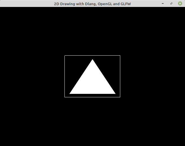
1.14 Minimal SDL project
The next code uses the SLD (Simple Direct Media Layer) library instead of GLFW for window system abstraction. The advantage of SDL over GLFW is that, SDL supports more platforms and is able to deal with audio and image loading, which are essential features for rich multimedia applications. This CMake script automatically downloads SDL and defines a macro for making it easier to create OpenGL apps with SDL statically linked.
SDL Web Sites:
- https://www.libsdl.org/
- https://github.com/libsdl-org/SDL (Repository)
- https://github.com/libSDL2pp/libSDL2pp (C++ Wrapper)
Project Files
File: CMakeLists.txt
cmake_minimum_required(VERSION 3.5)
project(OPENGL_SDL_project)

set(CMAKE_CXX_STANDARD 17)
set(CMAKE_CXX_STANDARD_REQUIRED ON)
set(CMAKE_VERBOSE_MAKEFILE ON)

#================ GLFW Settings  ===============#

find_package(OpenGL REQUIRED)

include(FetchContent)
# Download GLM (OpenGL math library for matrix and vectors transformation)
FetchContent_Declare(
  glm
  URL  https://github.com/g-truc/glm/archive/0.9.8.zip
)
FetchContent_MakeAvailable(glm)
include_directories(${glm_SOURCE_DIR} )

# Donwload library SLD - Simple Direct Media Layer
FetchContent_Declare(
  sdl
  URL    https://github.com/libsdl-org/SDL/archive/refs/tags/release-2.0.14.zip
)
FetchContent_MakeAvailable(sdl)
# find_package( SDL REQUIRED )

file(MAKE_DIRECTORY  ${sdl_SOURCE_DIR}/headers/SDL2)
file(COPY  ${sdl_SOURCE_DIR}/include/
           DESTINATION ${sdl_SOURCE_DIR}/headers/SDL2
           FILES_MATCHING PATTERN "*.h"
           )

               add_library( sdl-include  INTERFACE )
target_include_directories( sdl-include  INTERFACE ${sdl_SOURCE_DIR}/headers )
# Option for making this target IDE-friendly
IF(false)
target_sources( sdl-include INTERFACE
                              ${sdl_SOURCE_DIR}/headers/SDL2/SDL.h
                              ${sdl_SOURCE_DIR}/headers/SDL2/SDL_opengl.h
                           )

ENDIF()

# Download pre-compiled GLEW when building under Windows NT OS (x64)
IF(WIN32)
   FetchContent_Declare(
      glew-release
      URL   https://ufpr.dl.sourceforge.net/project/glew/glew/2.1.0/glew-2.1.0-win32.zip
      # https://github.com/nigels-com/glew/archive/glew-2.2.0.zip
   )
   FetchContent_MakeAvailable(glew-release)
   include_directories( ${glew-release_SOURCE_DIR}/include  ${glm_SOURCE_DIR} )
   link_directories(  ${glew-release_SOURCE_DIR}/lib/Release/x64 )

   set( GLEW_LIB_PATH1 ${glew-release_SOURCE_DIR}/lib/Release/x64/glew32.lib )
   set( GLEW_LIB_PATH2 ${glew-release_SOURCE_DIR}/lib/Release/x64/glew32s.lib )
ENDIF()

MACRO(ADD_OPENGL_APP target sources)
   add_executable( ${target} ${sources} )
   message([TRACE] " Add OpenGL executable = ${target} ")

   target_link_libraries( ${target} OpenGL::GL SDL2-static sdl-include
                                    ${GLEW_LIB_PATH1}
                                    ${GLEW_LIB_PATH2} )

    IF(MINGW)
        # Statically link against MINGW dependencies
        # for making easier to deploy on other machines.
        target_link_options( ${target} PRIVATE
                                 -static-libgcc
                                 -static-libstdc++
                                 -Wl,-Bstatic,--whole-archive -lwinpthread
                                   -Wl,--no-whole-archive
                                 )
     ENDIF()


     # Copy GLEW DLL shared library to same directory as the executable.
     IF(WIN32)
        add_custom_command(TARGET ${target} POST_BUILD
                       COMMAND ${CMAKE_COMMAND} -E copy_if_different
                       "${glew-release_SOURCE_DIR}/bin/Release/x64/glew32.dll"
                       $<TARGET_FILE_DIR:${target}>)
     ENDIF()
ENDMACRO()


      #========== Targets Configurations ================#

ADD_OPENGL_APP( opengl-sdl opengl-sdl.cpp )
File: xmake.lua (See: libsdl package)
add_rules("mode.debug", "mode.release")

add_requires("glm", "glew", "libsdl 2.0.14")

target("draw2d")
  set_kind("binary")
  add_files("./opengl-sdl.cpp")
  add_packages("glm", "glew", "libsdl")
File: opengl-sdl.cpp
#include <iostream>
#include <string>
#include <cassert>

#if defined(_WIN32)
   #include <windows.h>
   #include <GL/glew.h>
#endif

#define GL_GLEXT_PROTOTYPES 1
#define GL3_PROTOTYPES      1
#include <GL/gl.h>
#include <GL/glu.h>

#define SDL_MAIN_HANDLED
#include <SDL2/SDL.h>
#include <SDL2/SDL_opengl.h>

// --------- OpenGL Math Library ------------//
#include <glm/glm.hpp>
#include <glm/gtc/matrix_transform.hpp>
#include <glm/gtc/type_ptr.hpp>
#include <glm/gtx/string_cast.hpp>

// Wrapper for 2D vertex coordinates
struct Vertex2D{  GLfloat x, y;  };
// Wrapper for RGB colors
struct ColorRGB { GLfloat r, g, b; };

constexpr ColorRGB COLOR_R = { 1.0, 0.0, 0.0  }; // Red
constexpr ColorRGB COLOR_G = { 0.0, 1.0, 0.0  }; // Green
constexpr ColorRGB COLOR_B = { 0.0, 0.0, 1.0  }; // Blue

void compile_shader(GLuint m_program, const char* code, GLenum type);

void send_buffer( GLuint* pVao, GLuint* pVbo, GLsizei sizeBuffer
                , void* pBufffer, GLint   shader_attr, GLint size
                , GLenum type);

extern const char* shader_vertex;
extern const char* shader_fragment;

const glm::mat4 matrix_identity = glm::mat4(1.0);


int main()
{
    std::puts(" [TRACE] OpenGL SDL started Ok. ");

    int window_x = 100, window_y = 100, window_w = 500, window_h = 400;
    SDL_Window* window = SDL_CreateWindow(
                                "OpenGL with SLD library"
                               , window_x, window_y  // Window position
                               , window_w, window_h  // Window width and height
                               , SDL_WINDOW_OPENGL   // Bitwise-OR flags
                               );

    SDL_GLContext ctx = SDL_GL_CreateContext(window);

    // --- Initialize GLEW library after OpenGL context --------- //
    #if _WIN32
    glewExperimental = GL_TRUE;
    if (glewInit() != GLEW_OK) {
        std::cerr << "GLEW::Error : failed to initialize GLEW" << std::endl;
        std::abort();
    }
    std::fprintf(stderr, " [TRACE] Glew Initialized Ok. \n");
    #endif

    // ====== C O M P I L E  - S H A D E R ================== //

    GLuint prog = glCreateProgram();
    compile_shader(prog, shader_vertex,   GL_VERTEX_SHADER   ) ;
    compile_shader(prog, shader_fragment, GL_FRAGMENT_SHADER );
    glUseProgram(prog);

    // Get shader uniform variable location for projection matrix
    // See shader code: "uniform mat4 projection;"
    const GLint u_proj  = glGetUniformLocation(prog, "u_projection");
    assert( u_proj >= 0 && "Failed to find uniform variable" );

    // Get shader uniform variable  location for model matrix.
    const GLint u_model  = glGetUniformLocation(prog, "u_model");
    assert( u_model >= 0 && "Failed to find uniform variable" );

    // Get shader attribute location - the function glGetAttribLocation
    // returns (-1) on error.
    const GLint attr_position = glGetAttribLocation(prog, "position");
    assert( attr_position >= 0 && "Failed to get attribute location" );
    std::fprintf(stderr, " [TRACE] Attribute location attr_position = %d \n"
                , attr_position);

    // Get shader index of color attribute variable.
    const GLint attr_color = glGetAttribLocation(prog, "color");
    assert( attr_color >= 0);

    glUniformMatrix4fv(u_model, 1, GL_FALSE, glm::value_ptr(matrix_identity) );
    glUniformMatrix4fv(u_proj,  1, GL_FALSE, glm::value_ptr(matrix_identity) );

    // ======== U P L O A D - T O - G P U ==============================//

    constexpr size_t NUM_VERTICES = 3;

    float a = 0.25;

    Vertex2D vertices[NUM_VERTICES] = {
      {  0.0  ,   a * sqrt(3.0f) } // Vertex 0
    , { -2 * a,  -2 * a          } // Vertex 1
    , {  2 * a,  -2 * a          } // Vertex 2
    };

    ColorRGB colors[NUM_VERTICES] = {
          {0.4, 0.2, 0.67}
        , {0.8, 0.6, 0.30}
        , {0.2, 0.6, 0.10}
    };

    // Always initialize with zero (0), otherwise, the values
    // of those variables will be undefined. (Undefine Behavior)
    GLuint vao_triangle = 0;
    GLuint vbo_vertices = 0;
    GLuint vbo_colors   = 0;

    // Send vertices to GPU VBO (vbo_vertices)
    send_buffer(  &vao_triangle    // Ponter to VAO [OUTPUT]
                , &vbo_vertices    // Pointer VBO   [OUTPUT]
                , sizeof(vertices) // Size of buffer sent to GPU (VBO memory)
                , vertices         // Pointer to buffer
                , attr_position    // Shader attribute location
                , 2                // Each vertex has 2 coordinates (X, Y)
                , GL_FLOAT         // Each vertex coordinate has type GLfloat (float)
                );

    // Send colors to GPU VBO (vbo_colors)
    send_buffer(  &vao_triangle   // Pointer Vertex Array object
                , &vbo_colors     // Pointer Vertex buffer object handle (aka token)
                , sizeof(colors)  // Buffer size
                , colors          // Pointer to buffer (addrress of first buffer element)
                , attr_color      // Shader attribute location
                , 3               // Each color has 3 coordinates (R, G, B)
                , GL_FLOAT        // Each color coordiante has type GLfloat
                );

    glm::mat4 model;

    // ======== R E N D E R I N G - L O O P ============================//

    bool is_running = true;

    while( is_running )
    {
        SDL_Event event;
        // std::fprintf(stderr, " [TRACE] Waiting SDL event \n");

        while( SDL_PollEvent(&event) )
        {
            // std::fprintf(stderr, " [TRACE] Polling event \n");

            if( event.type == SDL_QUIT ){ is_running == false; }

            if( event.type == SDL_WINDOWEVENT
                && event.window.event == SDL_WINDOWEVENT_CLOSE )
            {  is_running = false;
               SDL_Quit();
            }
        }

        glViewport(0, 0, window_w, window_h);
        // OpenGL Background color (black for avoiding eye strain)
        glClearColor(0.0f, 0.0f, 0.0f, 1.0f);
        glClear(GL_COLOR_BUFFER_BIT);

        // === BEGIN REDERING ========//

            // ------ Draw triangle 1 ------ //
            glBindVertexArray(vao_triangle);
            model = matrix_identity;
            model = glm::translate(model, glm::vec3(0.35, 0.22, 0.0));
            glUniformMatrix4fv(u_model, 1, GL_FALSE, glm::value_ptr(model) );
            glDrawArrays(GL_TRIANGLES, 0, 3);

            // ------ Draw triangle 2 ------ //
            glBindVertexArray(vao_triangle);
            model = matrix_identity;
            model = glm::translate(model, glm::vec3(-0.5, -0.4, 0.0));
            model = glm::scale(model, glm::vec3(0.5, 0.5, 0.5 ) );
            model = glm::rotate(model, glm::radians(25.0f), glm::vec3(0.0, 0.0, 1.0) );
            glUniformMatrix4fv(u_model, 1, GL_FALSE, glm::value_ptr(model) );
            glDrawArrays(GL_TRIANGLES, 0, 3);

        // === END RENDERING ==========//

        SDL_GL_SwapWindow(window);
    }

    std::puts(" [TRACE] Shutdown gracefully. ");
    return 0;
}

// ----- I M P L E M E N T A T I O N S --------------//

    // ====== I M P L E M E N T A T I O N S ==========//

void compile_shader(GLuint m_program, const char* code, GLenum type)
{
    GLint shader_id = glCreateShader( type );
    glShaderSource(shader_id, 1, &code, nullptr);
    glCompileShader(shader_id);

    GLint is_compiled = GL_FALSE;
    // Check shader compilation result
    glGetShaderiv(shader_id, GL_COMPILE_STATUS, &is_compiled);

    // If there is any shader compilation result,
    // print the error message.
    if( is_compiled == GL_FALSE)
    {
        GLint length;
        glGetShaderiv(shader_id, GL_INFO_LOG_LENGTH, &length);
        assert( length > 0 );

        std::string out(length + 1, 0x00);
        GLint chars_written;
        glGetShaderInfoLog(shader_id, length, &chars_written, (char*) out.data());
        std::cerr << " [SHADER ERROR] = " << out << '\n';
        // Abort the exection of current process.
        std::abort();
    }

    glAttachShader(m_program, shader_id);
    glDeleteShader(shader_id);
    glLinkProgram(m_program);
    GLint link_status = GL_FALSE;
    glGetProgramiv(m_program, GL_LINK_STATUS, &link_status);
    assert( link_status != GL_FALSE );
    // glUseProgram(m_program);
}

// Upload buffer from main memory to GPU VBO
// =>> Parameters VAO, VBO are allocated by the caller.
void send_buffer( GLuint* pVao, GLuint* pVbo, GLsizei sizeBuffer
                , void* pBufffer, GLint   shader_attr, GLint size
                , GLenum type)
{
    assert(pVao != nullptr);
    assert(pVbo != nullptr);
    GLuint& vao = *pVao;
    GLuint& vbo = *pVbo;

    // Generate and bind current VAO (Vertex Array Object)
    if(vao == 0){ glGenVertexArrays(1, &vao); }
    glBindVertexArray(vao);

    // Generate and bind current VBO (Vertex Buffer Object)
    glGenBuffers(1, &vbo);
    glBindBuffer(GL_ARRAY_BUFFER, vbo);

    // Upload data to current VBO buffer in GPU
    glBufferData(GL_ARRAY_BUFFER, sizeBuffer, pBufffer, GL_STATIC_DRAW);
    glEnableVertexAttribArray(shader_attr);
    glVertexAttribPointer(shader_attr, size, type, GL_FALSE, 0, nullptr);

    // ------ Disable Global state set by this function -----//
    //
    // Unbind VAO
    glBindVertexArray(0);
    // Unbind VBO
    glBindBuffer(GL_ARRAY_BUFFER, vbo);
    // Disable current shader attribute
    glDisableVertexAttribArray(shader_attr);

}

// ----- S H A D E R S ------------------------------//

const char* shader_vertex = R"(
    #version 330 core

    layout ( location = 2)  in vec2 position;
    layout ( location = 1 ) in vec3 color;

    out vec3 out_color;
    uniform mat4 u_model;
    uniform mat4 u_projection;

    void main()
    {
       gl_Position = u_projection * u_model * vec4(position, 0, 1.0);
       out_color = color;
    }

 )";


const char* shader_fragment = R"(
    #version 330

    // This color comes from Vertex shader
    in vec3 out_color;

    void main()
    {
        // Set vertex colors
        gl_FragColor = vec4(out_color, 1.0);
    }

)";
Building
Building on Linux.
$ cmkae -H. -B_build_linux -DCMAKE_BUILD_TYPE=Debug
$ cmkae --build _build_linux --target
Building for Windows NT (cross-compilation) from Linux.
$ docker run -it --rm -v $PWD:/cwd -w /cwd --entrypoint=bash dockcross/windows-static-x64
$ cmake -H. -B_build_windows -DCMAKE_BUILD_TYPE=Debug
$ cmake --build _build_windows --target

$ ls
CMakeCache.txt  Makefile                 _deps                glew32.dll
CMakeFiles      SDL2ConfigVersion.cmake  cmake_install.cmake  opengl-sdl.exe
Run with wine:
$ wine _build_windows/opengl-sdl.exe
Building with Xmake:
 $ xmake -P .
[100%]: build ok!
Running the application: (default target)
$ xmake run -P .
[TRACE] OpenGL SDL started Ok.
[TRACE] Attribute location attr_position = 2
[TRACE] Shutdown gracefully.
Generate a CMake file and edit with VSCode or CLion:
$ xmake project -k cmake  -P .
create ok!

# Edit the project with VSCode
$ vscode .
1.15 Minimal Qt5 OpenGL project
Qt Framework is a better fit for non-games cross-platform OpenGL graphical applications like 3D drawing akin to Blender, CAD (Computer-Aided Design), scientific visualization and charts than GLFW, SDL or SFML as those window abstraction libraries lack widgets, such as buttons, menus, text entry and so on which are necessary for rich and complex interaction. Other significant advantage of Qt over the aforementioned libraries is that the Qt framework already has everything that is needed for developing OpenGL applications, including, OpenGL loading, 4x4 matrix, quaternion, OpenGL widget and scene graph.
Documentation:
- QOpenGLWindow class
- QOPenGLWidget class
- QOpenGLShaderProgram
- QVector3D class
- QVector4D class
- QQuaternion class
- QMatrix4x4 class
- Qt3D Core Module
Examples:
- https://doc.qt.io/qt-5/qtopengl-cube-example.html
- https://doc.qt.io/qt-5/qtopengl-2dpainting-example.html
- https://doc.qt.io/qt-5/qtgui-openglwindow-example.html
Screenshot
In this sample application, the vertex data is uploaded only once to the GPU via VBO (Vertex Buffer Object) and used for drawing two triangles, which the positions are set via affine trasnform objects. The program has tree buttons that controls the second triangle by performing the following set of operations: scale increasing; scale decreasing and rotation.
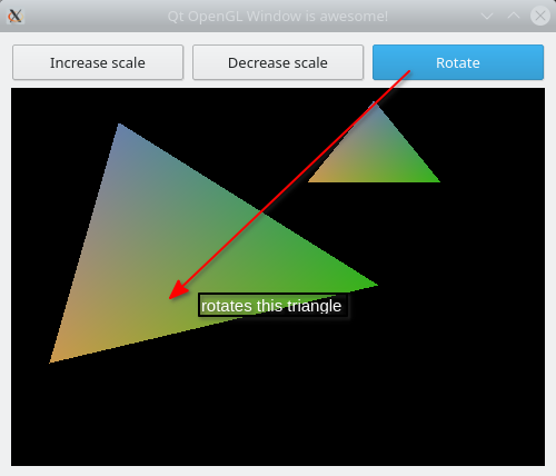
Figure 8: Minimal Qt 3D OpenGL application.
Project Files
File: CMakeLists.txt
cmake_minimum_required(VERSION 3.9)
project(Qt5_Widget_OpenGL)

#====== Global Configurations ==================#

set(CMAKE_CXX_STANDARD 17)
set(CMAKE_VERBOSE_MAKEFILE ON)
set(CMAKE_INCLUDE_CURRENT_DIR ON)
set(CMAKE_AUTOUIC ON)
set(CMAKE_AUTOMOC ON)
set(CMAKE_AUTORCC ON)
set(CMAKE_CXX_STANDARD_REQUIRED ON)

find_package(Qt5 COMPONENTS Core Widgets REQUIRED)

#=============== Target Configurations ============#
SET(QT5_LINK_LIBRARIES Qt5::Core Qt5::Gui Qt5::Widgets)

       add_executable( qt-opengl qt-opengl.cpp )
target_link_libraries( qt-opengl  Qt5::Core Qt5::Gui Qt5::Widgets )
File: meson.build (Note: poor IDE support) - For Meson Building System
- Docs: meson-tutorial qt5-meson
project('qt-opengl-meson', 'cpp')

qt5      = import('qt5')
qt5_deps = dependency('qt5', modules: ['Core', 'Gui', 'Widgets'] )

executable( 'qt-opengl'             # Executable name without extension
          , 'qt-opengl.cpp'         # Source files
          , dependencies: qt5_deps  # Depencies
          )
File: xmake.lua - For XMake building system
add_rules("mode.debug", "mode.release")

target("qt-opengl")
    add_rules("qt.widgetapp")
    set_languages("c99", "c++1z")
    add_files("qt-opengl.cpp")
File: qt-opengl.cpp
#include <iostream>
#include <functional>
#include <cassert>
#include <cmath>

#include <QtWidgets>
#include <QApplication>
#include <QOpenGLWindow>
#include <QOpenGLContext>
#include <QOpenGLBuffer>
#include <QOpenGLShaderProgram>


extern const char* shader_vertex;
extern const char* shader_fragment;

// Wrapper for 2D vertex coordinates
struct Vertex2D{  GLfloat x, y;  };
// Wrapper for RGB colors
struct ColorRGB { GLfloat r, g, b; };

struct Mesh
{
    QOpenGLBuffer*            vbo_vertex  = nullptr;
    QOpenGLBuffer*            vbo_color   = nullptr;
    QOpenGLVertexArrayObject* vao         = nullptr;
};

struct Transform
{
    QVector3D   position = {0.0,  0.0,  0.0,   };
    QVector3D   scale    = {1.0f, 1.0f, 1.0f   };
    QQuaternion rotation = {1.0, 0.0, 0.0, 0.0 };

    // Cached affine trasnform for speeding up computation
    // by tranding off time for space.
    QMatrix4x4 trasnform;

    // When this flag is true, the transform is computed again.
    bool is_changed = false;

    Transform& setPosition(float x, float y, float z)
    {
        position = {x, y, z};
        is_changed = true;
        return *this;
    }

    Transform& displace(float dx, float dy, float dz)
    {
        position = { position.x() + dx, position.y() + dy, position.z() + dz };
        is_changed = true;
        return *this;
    }

    Transform&  setRotationZ(float angle)
    {
        rotation = QQuaternion::fromAxisAndAngle( QVector3D{0.0, 0.0, 1.0}, angle );
        is_changed = true;
        return *this;
    }

    Transform& rotateZ(float angle)
    {
        rotation = rotation * QQuaternion::fromAxisAndAngle( QVector3D{0.0, 0.0, 1.0}, angle );
        is_changed = true;
        return *this;
    }

    Transform& setScale(float f)
    {
        scale = {f, f, f};
        is_changed = true;
        return *this;
    }

    Transform& addScale(float f)
    {
        scale = { scale.x() + f, scale.y() + f, scale.z() + f };
        is_changed = true;
        return *this;
    }

    QMatrix4x4 value()
    {

        if( is_changed )
        {
            std::fprintf(stderr, " [TRACE] Affine transform recalculated. Ok. \n");
            trasnform.setToIdentity();
            trasnform.translate( position );
            trasnform.scale(scale);
            trasnform.rotate(rotation);
            is_changed = false;
        }
        return trasnform;
    }
};

class OpenGLCanvas: public QOpenGLWidget
{
public:
     using DrawCallback = std::function<void (QOpenGLExtraFunctions* ctx)>;
private:
    QOpenGLShaderProgram* m_prog    = nullptr;


    // Shader attribute location
    int attr_position = 0;
    int attr_color    = 0;
    // Shader uniform locations
    int u_model = 0;
    int u_proj  = 0;

    DrawCallback m_callback = [](QOpenGLExtraFunctions* ){ };
    DrawCallback m_init     = [](QOpenGLExtraFunctions* ){ };
public:

    OpenGLCanvas(DrawCallback init):  m_init(init){ }

    void initializeGL() override
    {
        auto ctx = QOpenGLContext::currentContext()->extraFunctions();
        std::fprintf(stderr, " [TRACE] Initialized Ok. \n");

        m_prog = new QOpenGLShaderProgram;
        m_prog->addShaderFromSourceCode(QOpenGLShader::Vertex,   shader_vertex);
        m_prog->addShaderFromSourceCode(QOpenGLShader::Fragment, shader_fragment);
        m_prog->link();
        m_prog->bind();
        // Attribute location
        attr_position = m_prog->attributeLocation("position");
        Q_ASSERT( attr_position != -1 );
        attr_color = m_prog->attributeLocation("color");
        Q_ASSERT( attr_color != -1    );

        // Uniform variables
        u_model = m_prog->uniformLocation("u_model");
        Q_ASSERT( u_model != -1 );
        u_proj  = m_prog->uniformLocation("u_proj");
        Q_ASSERT( u_proj != -1 );

        // Initialize shader uniform variables
        QMatrix4x4 m;
        m.setToIdentity();
        m_prog->setUniformValue(u_model, m);
        m_prog->setUniformValue(u_proj,  m);

        m_init(ctx);
   }

    void setDrawCallback(DrawCallback callback)
    {
        m_callback = callback;
    }

    // Override QOpenGLWidget::paintGL()
    void paintGL() override
    {
        std::fprintf(stderr, " [TRACE] Painting window Ok. \n");

        QOpenGLExtraFunctions* ctx = QOpenGLContext::currentContext()->extraFunctions();
        ctx->glClearColor(0.0, 0.0, 0.0, 1.0);
        ctx->glClear( GL_COLOR_BUFFER_BIT | GL_DEPTH_BUFFER_BIT );

        m_callback(ctx);
    }

    // Override QOpenGLWidget::resizeGL()
    void resizeGL(int w, int h) override
    {
        std::fprintf(stderr, " [TRACE] Window resized. \n");

        // Forward call to superclass
        this->QOpenGLWidget::resizeGL(w, h);
    }

    // Set model matrix of current object
    void setModel(QMatrix4x4 const& m){ m_prog->setUniformValue(u_model, m); }

    // Upload vertices to GPU
    Mesh upload(size_t num_vertices, Vertex2D* vertices, ColorRGB* colors)
    {
        auto ctx = QOpenGLContext::currentContext()->extraFunctions();

        auto vao = new QOpenGLVertexArrayObject;
        if( vao->create() ){ vao->bind(); }

        // Send vertices positions to GPU
        auto vbo_vertex = new QOpenGLBuffer;
        vbo_vertex->create();
        vbo_vertex->bind();
        vbo_vertex->allocate( vertices , num_vertices * sizeof(Vertex2D) );
        ctx->glEnableVertexAttribArray(attr_position);
        // Set data layout, how the data will be interpreted.
        ctx->glVertexAttribPointer( attr_position, 2, GL_FLOAT, GL_FALSE, 0, nullptr );

        // Send vertices colors to GPU
        auto vbo_color = new QOpenGLBuffer;
        vbo_color->create();
        vbo_color->bind();
        vbo_color->allocate( colors, num_vertices * sizeof(ColorRGB));
        ctx->glEnableVertexAttribArray(attr_color);
        // Set color data layout
        ctx->glVertexAttribPointer( attr_color, 3, GL_FLOAT, GL_FALSE, 0, nullptr );

        Mesh mesh;
        mesh.vbo_vertex = vbo_vertex;
        mesh.vbo_color  = vbo_color;
        mesh.vao = vao;
        return mesh;
    }
};


int main(int argc, char** argv)
{
    std::cout << " [INFO] Starting Application" << std::endl;

    QApplication app(argc, argv);
    app.setApplicationName("Qt OpenGL Cavans");

    constexpr size_t NUM_VERTICES = 3;

    const float a = 0.5f ;

    Vertex2D vertices[NUM_VERTICES] = {
          {  0.0,  a * sqrtf(3.0f) } // Vertex 0
        , {   -a,  0.0             } // Vertex 1
        , {    a,  0.0             } // Vertex 2
    };

    ColorRGB colors[NUM_VERTICES] = {
          {0.4, 0.5, 0.67}
        , {0.8, 0.6, 0.30}
        , {0.2, 0.7, 0.10}
    };


    QWidget window;
    window.resize(500, 400);
    window.setWindowTitle("Qt OpenGL Window is awesome!");

    auto hbox = new QVBoxLayout(&window);

    auto form = new QHBoxLayout();
    auto btn_add_scale = new QPushButton("Increase scale");
    auto btn_dec_scale = new QPushButton("Decrease scale");
    auto btn_rotate = new QPushButton("Rotate");
    form->addWidget(btn_add_scale);
    form->addWidget(btn_dec_scale);
    form->addWidget(btn_rotate);
    hbox->addLayout(form);

    Mesh mesh_triangle;

    Transform trf_triangle1;
    trf_triangle1.setPosition(0.36f, 0.50f, 0.0f)
                 .rotateZ(0)
                 .setScale(0.50);


    Transform trf_triangle2;
    trf_triangle2.setPosition(-0.24, -0.25, 0.0)
                 .setScale(0.80)
                 .rotateZ(35.0);

    qDebug() << " Trasnform 1 = " << trf_triangle1.value();
    qDebug() << " Transform 2 = " << trf_triangle2.value();

    OpenGLCanvas* canvas = new OpenGLCanvas([&](QOpenGLExtraFunctions* ctx)
    {
        mesh_triangle = canvas->upload(NUM_VERTICES, vertices, colors);
    });
    canvas->setSizePolicy(QSizePolicy::Expanding, QSizePolicy::Expanding);
    hbox->addWidget(canvas);

    canvas->setDrawCallback([&](QOpenGLExtraFunctions* ctx)
    {
        // Draw triangle 1
        mesh_triangle.vao->bind();
        // canvas->setModel(model_triangle1);
        canvas->setModel( trf_triangle1.value() );
        ctx->glDrawArrays(GL_TRIANGLES, 0, NUM_VERTICES);

        // Draw triangle 2
        mesh_triangle.vao->bind();
        // canvas->setModel(model_triangle2);
        canvas->setModel( trf_triangle2.value() );
        ctx->glDrawArrays(GL_TRIANGLES, 0, NUM_VERTICES);
    });

    window.show();


    // ----------- Set events ----------------------//

    QObject::connect(btn_add_scale, &QPushButton::clicked,
             [&]{
                   std::fprintf(stderr, " [TRACE] Button to increase scale clicked. Ok. \n");
                   trf_triangle2.addScale(+0.10);
                   canvas->repaint();
             });

    QObject::connect(btn_dec_scale, &QPushButton::clicked,
                     [&]{
                        std::fprintf(stderr, " [TRACE] Button to decrease scale clicked. Ok. \n");
                        trf_triangle2.addScale(-0.10);
                        canvas->repaint();
                     });

    QObject::connect(btn_rotate, &QPushButton::clicked,
                     [&]{
                         std::fprintf(stderr, " [TRACE] Button to rotate triangle clicked. Ok. \n");
                         trf_triangle2.rotateZ(10.5);
                         canvas->repaint();
                     });

    return app.exec();
}


// ===== S H A D E R - P R O G R A M S ==========//


const char* shader_vertex = R"(
    #version 330 core

    layout ( location = 2)  in vec2 position;
    layout ( location = 1 ) in vec3 color;

    out vec3 out_color;
    uniform mat4 u_model;
    uniform mat4 u_proj;

    void main()
    {
       gl_Position = u_proj * u_model * vec4(position, 0, 1.0);
       out_color = color;
    }

 )";


const char* shader_fragment = R"(
    #version 330

    // This color comes from Vertex shader
    in vec3 out_color;

    void main()
    {
        // Set vertex colors
        gl_FragColor = vec4(out_color, 1.0);
    }

)";
Building with CMake
 # Build application
 $ cmake -H. -B_build -DCMAKE_BUILD_TYPE=Debug
 $ cmake --build _build --target all

 # List build tree directory
 $ >> ls _build/
CMakeCache.txt  cmake_install.cmake  qt-opengl*
CMakeFiles/     Makefile             qt-opengl_autogen/

# Run application
$ >> _build/qt-opengl
Building with Meson
# Build application
$ meson setup _build_meson # Name of build directory is arbitrary
$ meson compile -C _build_meson

# List build directory
$ >> ls _build_meson/
build.ninja            meson-info/  meson-private/  qt-opengl.p/
compile_commands.json  meson-logs/  qt-opengl*

# Run application
$ >> ./_build_meson/qt-opengl
Building with XMake
Build project with Xmake lua-based building system showing all compilation and linking process.
$ xmake build -v
Run application (default target):
$ xmake run
Run application specifying the target:
$ xmake run qt-opengl
Generate an CMakeLists.txt for making IDEs and smart text editors including, CLion, QtCreator and Visual Studio Code happy.
$ >> xmake project -k cmake
create ok!

# Edit project with Visual Studio Code
$ code .

# Edit project with CLion
=>> Open the project directory with CLion

# Edit project with QtCreator
=>> Open the project directory with Qt creator
$ qt-creator .

# Build project with CMakeLists.txt
$ cmake -H. -B_build -DCMAKE_BUILD_TYPE=Debug
$ cmake --build _build --target
1.16 Minimal WebGL-OpenGL project
WebGL is a web standard supported by most modern web browsers for a low-level 3D graphics API accelerated by GPU based on OpenGL ES. By using WebGL as in this next code, it is possible to play with OpenGL 3D computer graphics without the hassle of dealing with C or C++ compilation and building systems since WebGL API is already available in any web browser and the API is exposed as JavaScript API, that resembles OpenGL C API.
- Live example available at: https://jsfiddle.net/prxbmqof/
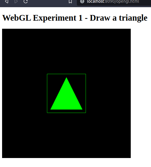
Complete Html Code
<!DOCTYPE html>
<html>
   <head>
       <title> Web Page Title </title>
       <script src="https://somehost.com/jequey.js"></script>

   </head>

   <body>
       <h1>WebGL Experiment 1 - Draw a triangle</h1>
       <canvas id="glCanvas" width="480" height="480">
   </body>
  <script>
    // Source: https://webglfundamentals.org/webgl/lessons/webgl-fundamentals.html
    function createShader(gl, type, source)

      ... ... ... ... ... ... ... ... ... ... ..
      ... ... ... ... ... ... ... ... ... ... ...

    // Draw Square
    console.log(" [TRACE] Draw sqaure in WebGL");
    gl.bindBuffer( gl.ARRAY_BUFFER, vbo_square );
    gl.vertexAttribPointer(attr_position, 2, gl.FLOAT, false, 0, 0);
    gl.drawArrays(gl.LINE_LOOP, 0, 4);

    console.log(" [TRACE] Loaded Ok.");
  </script>

</html>
JavaScript part:
// Source: https://webglfundamentals.org/webgl/lessons/webgl-fundamentals.html
function createShader(gl, type, source)
{
  var shader = gl.createShader(type);
  gl.shaderSource(shader, source);
  gl.compileShader(shader);
  var success = gl.getShaderParameter(shader, gl.COMPILE_STATUS);
  if (success) {
    return shader;
  }

  console.log(gl.getShaderInfoLog(shader));
  gl.deleteShader(shader);
}

// Source:  https://webglfundamentals.org/webgl/lessons/webgl-fundamentals.html
function createProgram(gl, vertexShader, fragmentShader)
{
  var program = gl.createProgram();
  gl.attachShader(program, vertexShader);
  gl.attachShader(program, fragmentShader);
  gl.linkProgram(program);
  var success = gl.getProgramParameter(program, gl.LINK_STATUS);
  if (success) {
    return program;
  }

  console.log(gl.getProgramInfoLog(program));
  gl.deleteProgram(program);
}


function resizeCanvasToDisplaySize(canvas, multiplier)
{
    multiplier = multiplier || 1;
    const width  = canvas.clientWidth  * multiplier | 0;
    const height = canvas.clientHeight * multiplier | 0;
    if (canvas.width !== width ||  canvas.height !== height) {
      canvas.width  = width;
      canvas.height = height;
      return true;
    }
    return false;
  }


const canvas = document.querySelector("#glCanvas");
const gl = canvas.getContext("webgl");

if(  gl == null ){
  alert(" [ABORT] Unable to initialized WebGL");
}

// Vertex Shader code => Performs vertex coordinate transforms in the GPU
// Defines the a 3D scene or 2D scene (by ignoring the Z axis).
let code_shader_vertex = `
  attribute vec2 position;

  void main(){
     // Coordinates: X, Y, Z = 0, W = 1 => Ignores the Z axis (2D Scene)
     gl_Position = vec4(position, 0, 1.0);

  }
`;

// Fragment shader code => Sets color, lights and illumination
let code_shader_fragment = `
  void main(){
    // Color always green
    // Color in (R, G, B, W) => (Red, Green, Blue, W)
    gl_FragColor = vec4(0.0, 1.0, 0.0, 1.0);
  }
`;

// Vertices of (x, y) coordinates
let vertices_triangle = [
    -0.25, -0.25
  ,  0.00,  0.25
  ,  0.25, -0.25
];

let vertices_square = [
    -0.3, -0.3
  , -0.3,  0.3
  ,  0.3,  0.3
  ,  0.3, -0.3

];


let shader_vert = createShader(gl, gl.VERTEX_SHADER, code_shader_vertex);
let shader_frag = createShader(gl, gl.FRAGMENT_SHADER, code_shader_fragment);
let prog = createProgram(gl, shader_vert, shader_frag);

let attr_position = gl.getAttribLocation(prog, "position");
console.log(" [TRACE] attr_position = ", attr_position);

// resizeCanvasToDisplaySize(gl.canvas);
gl.viewport(0, 0, gl.canvas.width, gl.canvas.height);

// Screen background color is black => clearColor(Red intensity from 0 to 1, Green , Blue , Alpha)
gl.clearColor(0.0, 0.0, 0.0, 1.0);
gl.clear(gl.COLOR_BUFFER_BIT);
gl.useProgram(prog);

// -------- Upload triangle to GPU --------------------//
// GLuint vbo_triangle_ = 0;
// glGenBuffers(1 , &vbo_triangle_);
let vbo_triangle = gl.createBuffer();
// Set this buffer as current buffer (global state)
gl.bindBuffer( gl.ARRAY_BUFFER, vbo_triangle );
// Upload vertices to  GPU
gl.bufferData(gl.ARRAY_BUFFER, new Float32Array(vertices_triangle), gl.STATIC_DRAW);

// --------- Upload squares to GPU ----------------------//
let vbo_square = gl.createBuffer();
gl.bindBuffer( gl.ARRAY_BUFFER, vbo_square );
gl.bufferData(gl.ARRAY_BUFFER, new Float32Array(vertices_square), gl.STATIC_DRAW);

// ------ Drawing ----------------------------------------//
gl.enableVertexAttribArray(attr_position);

// Draw triangle
console.log(" [TRACE] Draw triangle in WebGL");
gl.bindBuffer( gl.ARRAY_BUFFER, vbo_triangle );
gl.vertexAttribPointer(attr_position, 2, gl.FLOAT, false, 0, 0);
gl.drawArrays(gl.TRIANGLES, 0, 3);

// Draw Square
console.log(" [TRACE] Draw sqaure in WebGL");
gl.bindBuffer( gl.ARRAY_BUFFER, vbo_square );
gl.vertexAttribPointer(attr_position, 2, gl.FLOAT, false, 0, 0);
gl.drawArrays(gl.LINE_LOOP, 0, 4);

console.log(" [TRACE] Loaded Ok.");
1.17 Loading OpenGL without Glew
The next code loads OpenGL function pointers without Glew (OpenGL extension wrangler) for streamlining the building process. Glew is a library for loading OpenGL function pointers and OpenGL extensions in a platform-agnostic way. Despite the usefulness of this library, its source code is hard to integrate to building systems as the Glew building systems as Glew library needs Perl and other dependencies for code generation.
Relevant documentation:
- Khronos Group - Load OpenGL Functions
- Brief: "Loading OpenGL Functions is an important task for initializing OpenGL after creating an OpenGL context. You are strongly advised to use an OpenGL Loading Library instead of a manual process. However, if you want to know how it works manually, read on."
- Why are OpenGL functions loaded at runtime …?
- When do I need to use an OpenGL function loader?
- MSDN - wglGetProcAddress (WGL - Windows NT)
- Brief: "The wglGetProcAddress function returns the address of an OpenGL extension function for use with the current OpenGL rendering context."
- MSDN - wglGetCurrentContext (WGL - Windows NT)
- Brief: "The wglGetCurrentContext function obtains a handle to the current OpenGL rendering context of the calling thread."
- wglGetProcAddress returns NULL
Screenshot
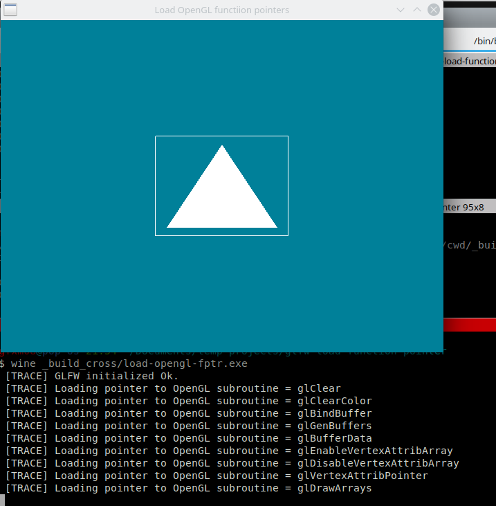
Files
File: CMakeListst.txt
cmake_minimum_required(VERSION 3.5)
project(OpenGL_Load_FPTR)

set(CMAKE_CXX_STANDARD 17)
set(CMAKE_CXX_STANDARD_REQUIRED ON)
set(CMAKE_VERBOSE_MAKEFILE ON)

#================ GLFW Settings  ===============#

find_package(OpenGL REQUIRED)

include(FetchContent)

# Set GLFW Options before FectchContent_MakeAvailable
set( GLFW_BUILD_EXAMPLES OFF CACHE BOOL  "GLFW lib only" )
set( GLFW_BUILD_TESTS    OFF CACHE BOOL  "GLFW lib only" )
set( GLFW_BUILD_DOCS     OFF CACHE BOOL  "GLFW lib only" )
set( GLFW_BUILD_INSTALL  OFF CACHE BOOL  "GLFW lib only" )

# Donwload GLFW library
FetchContent_Declare(
  glfwlib
  URL   https://github.com/glfw/glfw/releases/download/3.3.2/glfw-3.3.2.zip
)
FetchContent_MakeAvailable(glfwlib)

MACRO(ADD_OPENGL_APP target sources)
   add_executable( ${target} ${sources} )
   message([TRACE] " Add OpenGL executable = ${target} ")

   target_link_libraries( ${target} glfw OpenGL::GL)

    IF(MINGW)
        # Statically link against MINGW dependencies
        # for making easier to deploy on other machines.
        target_link_options( ${target} PRIVATE
                                 -static-libgcc
                                 -static-libstdc++
                                 -Wl,-Bstatic,--whole-archive -lwinpthread
                                   -Wl,--no-whole-archive
                                 )
     ENDIF()

ENDMACRO()

     # ======= T A R G E T S ============================#
     #                                                   #

ADD_OPENGL_APP( load-opengl-fptr  load-opengl-fptr.cpp )
File: load-openg-fptr.cpp
// ----- Manual Loading of OpenGL function pointers -------//
#include <iostream>
#include <vector>
#include <array>
#include <cmath>
#include <cassert>

// -------- OpenGL headers ---------//
//
#define GL_GLEXT_PROTOTYPES 1 // Necessary for OpenGL >= 3.0 functions
#define GL3_PROTOTYPES      1 // Necessary for OpenGL >= 3.0 functions


#if defined(_WIN32)
   #include <windows.h>
#endif

#include <GL/gl.h>

#if defined(__linux__) || defined(__bsd__)
    #include <GL/glx.h>  // For glXGetProcAddress() and glXGetProcAddressARB()
    #include <GL/glxext.h>
#endif

#include <GL/glu.h>
#include <GLFW/glfw3.h>


//======== B O I L E R P L A T E - F O R - L O A D I N G - O P E N G L ==========//
//

#define GL_ARRAY_BUFFER  0x8892
#define GL_STATIC_DRAW   0x88E4

// Generic void function pointer which can be casted to any other function pointer.
using FptrVoid = void*;

/** @brief Load OpenGL function pointer at runtime
  * See:
  *    -
  *    - https://stackoverflow.com/questions/21769427/wglgetprocaddress-returns-null
  */
FptrVoid load_gl_function(const char* name)
{
    FptrVoid fp = nullptr;
    std::fprintf(stderr, " [TRACE] Loading pointer to OpenGL subroutine = %s \n", name);

    #if defined(_WIN32)
        assert( wglGetCurrentContext() != nullptr && "Current thread lacks a OpenGL rendering context." );

        fp = (void*) wglGetProcAddress(name);
        // assert( fp != nullptr );
        if( fp == 0
            || (fp == (void*)0x1) || (fp == (void*)0x2) || (fp == (void*)0x3)
            || (fp == (void*)-1) )
          {
            HMODULE module = LoadLibraryA("opengl32.dll");
            fp = (void *) GetProcAddress(module, name);
          }

        if( fp == nullptr)
        {
            std::fprintf(stderr, " [ERROR] OpenGL function = '%s' not found on Windows ", name );
            std::abort();
        }
    #elif defined(__linux__) || defined(__bsd__)
        fp = (FptrVoid) glXGetProcAddressARB( (const unsigned char*) name);

        if( fp == nullptr )
        {
            std::fprintf(stderr, " [ERROR] OpenGL function not found on Linux or BSD " );
            std::abort();
        }
    #endif
    return fp;
}

typedef unsigned int    GLenum;
typedef unsigned char   GLboolean;
typedef unsigned int    GLbitfield;
typedef void        GLvoid;
typedef signed char GLbyte;     /* 1-byte signed */
typedef short       GLshort;    /* 2-byte signed */
typedef int     GLint;      /* 4-byte signed */
typedef unsigned char   GLubyte;    /* 1-byte unsigned */
typedef unsigned short  GLushort;   /* 2-byte unsigned */
typedef unsigned int    GLuint;     /* 4-byte unsigned */
typedef int     GLsizei;    /* 4-byte signed */
typedef float       GLfloat;    /* single precision float */
typedef float       GLclampf;   /* single precision float in [0,1] */
typedef double  GLdouble;   /* double precision float */
typedef double  GLclampd;   /* double precision float in [0,1] */

#ifdef _WIN64
    typedef signed   long long int khronos_intptr_t;
    typedef unsigned long long int khronos_uintptr_t;
    typedef signed   long long int khronos_ssize_t;
    typedef unsigned long long int khronos_usize_t;
#else
    typedef signed   long  int     khronos_intptr_t;
    typedef unsigned long  int     khronos_uintptr_t;
    typedef signed   long  int     khronos_ssize_t;
    typedef unsigned long  int     khronos_usize_t;
#endif


typedef khronos_ssize_t GLsizeiptr;
typedef khronos_intptr_t GLintptr;

using glClear_t = void (*) ( unsigned int mask );
using glClearColor_t = void (*) ( float red, float green, float blue, float alpha );
using glBindBuffer_t = void (*) (GLenum target, GLuint buffer);
using glGenBuffers_t = void (*) (GLsizei n, GLuint * buffers);
using glBufferData_t = void (*) (GLenum target, GLsizeiptr size, const void *data, GLenum usage);
using glEnableVertexAttribArray_t = void (*) (GLuint index);
using glDisableVertexAttribArray_t = void (*) (GLuint index);
using glVertexAttribPointer_t = void (*) (GLuint index, GLint size, GLenum type, GLboolean normalized, GLsizei stride, const void *pointer);
using glDrawArrays_t = void (*) ( GLenum mode, GLint first, GLsizei count );

struct OpenGL {

    OpenGL() {
        this->glClear = reinterpret_cast<glClear_t>( load_gl_function("glClear") );
        // It should be used reinterpret_cast<>, but C-style cast is used for breviety.
        this->glClearColor = (glClearColor_t) load_gl_function("glClearColor");
        this->glBindBuffer = (glBindBuffer_t) load_gl_function("glBindBuffer");
        this->glGenBuffers = (glGenBuffers_t) load_gl_function("glGenBuffers");
        this->glBufferData = (glBufferData_t) load_gl_function("glBufferData");
        this->glEnableVertexAttribArray   = (glEnableVertexAttribArray_t) load_gl_function("glEnableVertexAttribArray");
        this->glDisableVertexAttribArray  = (glDisableVertexAttribArray_t) load_gl_function("glDisableVertexAttribArray");
        this->glVertexAttribPointer       = (glVertexAttribPointer_t) load_gl_function("glVertexAttribPointer");
        this->glDrawArrays                = (glDrawArrays_t) load_gl_function("glDrawArrays");

    }

    glClear_t               glClear;
    glClearColor_t                glClearColor;
    glBindBuffer_t              glBindBuffer;
    glGenBuffers_t              glGenBuffers;
    glBufferData_t                  glBufferData;
    glEnableVertexAttribArray_t   glEnableVertexAttribArray;
    glDisableVertexAttribArray_t  glDisableVertexAttribArray;
    glVertexAttribPointer_t         glVertexAttribPointer;
    glDrawArrays_t                glDrawArrays;
};

// ====== S T A R T - O F - A P P L I C A T I O N - C O D E ============//
//

struct Vertex2D
{
    GLfloat x;
    GLfloat y;
};

int main(int argc, char** argv)
{


    GLFWwindow* window;

    // Initialize GLFW
    if (!glfwInit()){ return -1; }

    std::fprintf(stderr, " [TRACE] GLFW initialized Ok. \n");


    /* Create a windowed mode window and its OpenGL context */
    window = glfwCreateWindow(640, 480, "Load OpenGL functiion pointers", NULL, NULL);
    if (!window)
    {
        glfwTerminate();
        return -1;
    }

    // ----- Before defining current OpenGL context ----//
        glfwMakeContextCurrent(window);
    // ----- After defining current OpenGL context -----//

    // GL object Must only be instantiated after an OpenGL context (Window) is obtained
    OpenGL gl;

    gl.glClearColor(0.0f, 0.5f, 0.6f, 1.0f);

    Vertex2D triangle_points[3] = {
        Vertex2D{-0.25,   -0.25}
      , Vertex2D{ 0.00,   0.25}
      , Vertex2D{ 0.25,  -0.25}
    };

    Vertex2D square_points[4] = {
        { -0.3,  -0.3 }
      , { -0.3,   0.3 }
      , {  0.3,   0.3 }
      , {  0.3,  -0.3 }
    };

    // ================== Triangle Buffer ====================//
    //

    GLuint vbo_triangle_ = 0;

    // Create an OpenGL VBO buffer
    gl.glGenBuffers(1, &vbo_triangle_ );
    assert( vbo_triangle_ != 0 );
    gl.glBindBuffer(GL_ARRAY_BUFFER, vbo_triangle_);
    gl.glBufferData(GL_ARRAY_BUFFER, sizeof(triangle_points), triangle_points, GL_STATIC_DRAW);
    gl.glBindBuffer(GL_ARRAY_BUFFER, 0);

    // ================ Square / Vertex Buffer Object 2 ==================//
    //

    GLuint vbo_square_ = 0;
    gl.glGenBuffers(1, &vbo_square_);
    // Check for error
    assert( vbo_square_ != 0);
    gl.glBindBuffer(GL_ARRAY_BUFFER, vbo_square_);
    gl.glBufferData(GL_ARRAY_BUFFER, sizeof(square_points), square_points, GL_STATIC_DRAW);
    gl.glBindBuffer(GL_ARRAY_BUFFER, 0);

    GLint shader_attr = 0;

    //  ======= R E N D E R  - L O O P ============//
    //
    while ( !glfwWindowShouldClose(window) )
    {
            gl.glClear(GL_COLOR_BUFFER_BIT);

        // ====== BEGIN RENDERING ============//

            // ------------ Draw triangle --------------//
            //
            gl.glBindBuffer(GL_ARRAY_BUFFER, vbo_triangle_);
            gl.glEnableVertexAttribArray(shader_attr);

            gl.glVertexAttribPointer(shader_attr, 2, GL_FLOAT, GL_FALSE, 0, nullptr);
            glDrawArrays(GL_TRIANGLES, 0, 3);

            // Disable global state
            gl.glBindBuffer(GL_ARRAY_BUFFER, 0);
            gl.glDisableVertexAttribArray(0);

            //------------ Draw Square -------------------------//
            //

            #if 1
            gl.glBindBuffer(GL_ARRAY_BUFFER, vbo_square_);
            gl.glEnableVertexAttribArray(shader_attr);
            gl.glVertexAttribPointer(0, 2, GL_FLOAT, GL_FALSE, 0, nullptr);
            // Plot 4 vertices
            gl.glDrawArrays(GL_LINE_LOOP, 0, 4);

            // Disable global state
            gl.glBindBuffer(GL_ARRAY_BUFFER, 0);
            gl.glDisableVertexAttribArray(shader_attr);
            #endif

        // ====== END RENDERING ==============//

        /* Swap front and back buffers */
        glfwSwapBuffers(window);
        /* Poll for and process events */
        glfwPollEvents();

        if( glfwGetKey(window, 'Q' ) == GLFW_PRESS )
        {
             std::cout << " [TRACE] User typed Q =>> Shutdown program. Ok. " << '\n';
             break;
        }
    }

    glfwTerminate();
    return 0;
}
Building
Building on Linux:
$ cmake -H. -B_build_linux -DCMAKE_BUILD_TYPE=Debug
$ cmake --build _build_linux --target
Building for Windows with Dockercross tool:
$ docker run -it --rm -v $PWD:/cwd -w /cwd --entrypoint=bash dockcross/windows-static-x64
$ cmake -H. -B_build_cross -DCMAKE_BUILD_TYPE=Debug
$ cmake --build _build_cross --target

$ wine _build_cross/load-opengl-fptr.exe
 [TRACE] GLFW initialized Ok.
 [TRACE] Loading pointer to OpenGL subroutine = glClear
 [TRACE] Loading pointer to OpenGL subroutine = glClearColor
 [TRACE] Loading pointer to OpenGL subroutine = glBindBuffer
 [TRACE] Loading pointer to OpenGL subroutine = glGenBuffers
 [TRACE] Loading pointer to OpenGL subroutine = glBufferData
 [TRACE] Loading pointer to OpenGL subroutine = glEnableVertexAttribArray
 [TRACE] Loading pointer to OpenGL subroutine = glDisableVertexAttribArray
 [TRACE] Loading pointer to OpenGL subroutine = glVertexAttribPointer
 [TRACE] Loading pointer to OpenGL subroutine = glDrawArrays
1.18 2D - using VAO
A VAO (Vertex Array Object) is an object that stores all the information necessary to render a VBO (Vertex Buffer Object). For instance, a VAO allows rendering the data, by performing the following set of operations only once: 1 - binding the VAO; 2 - binding the buffer via glBindBuffer() call; 3 - enabling the vertex attribute via glEnableVertexAttribArray(); 4 - setting the data layout by calling glVertexAttribPointer() subroutine. Without a VAO, all those subroutines would need to be called on every frame rendering.
Algorithm for VAO usage:
- Setup
// Shader attribute location
GLint shader_attr = 1;

// -------------- Setup VAO --------------------//
//
GLuint vao;
glGenVertexArrays(1, &vao); // Instantiate VAO

GLuint vbo;
glGenBuffers(1, &vbo);
// Bind VBO (Recorded by VAO)
glBindBuffer(GL_ARRAY_BUFFER, vbo);

// Upload data to GPU
glBufferData(GL_ARRAY_BUFFER, buffer_size, buffer, GL_STATIC_DRAW);

glEnableVertexAttribArray(shader_attr);

// Set buffer data layout (Recorded by VAO)
glVertexAttribPointer(shader_attr, size, type, GL_FALSE, 0, nullptr);

// ------- Disable Global state ---------//

// Unbind VAO
glBindVertexArray(0);
// Unbind VBO
glBindBuffer(GL_ARRAY_BUFFER, vbo);
// Disable current shader attribute
glDisableVertexAttribArray(shader_attr);
- Rendering loop
     ... ...         ... ...         ... ...
     ... ...         ... ...         ... ...

//  ======= R E N D E R  - L O O P ============//
//                                             //
while ( !glfwWindowShouldClose(window) )
{
    glClear(GL_COLOR_BUFFER_BIT);
     ... ...         ... ...         ... ...
     ... ...         ... ...         ... ...

     glBindVertexArray(vao);
     glDrawArrays(GL_LINE_LOOP, 0, NUMBER_OF_VERTICES);

     glBindVertexArray(vao1);
     glDrawArrays(GL_LINE_TRIANGLES, 0, NUMBER_OF_VERTICES_1);

     glBindVertexArray(vao2);
     glDrawArrays(GL_LINES, 0, NUMBER_OF_VERTICES_2);

     ... ...         ... ...         ... ...
     ... ...         ... ...         ... ...

    /* Swap front and back buffers */
    glfwSwapBuffers(window);
    /* Poll for and process events */
    glfwPollEvents();
}
Further Reading
- Tutorial2: VAOs, VBOs, Vertex and Fragment Shaders (C / SDL) - OpenGL Wiki
- Android Developers Blog: Game Performance: Vertex Array Objects
- Android Developers Blog: Game Performance: Layout Qualifiers
- c++ - Process of setting up a VAO in OpenGL - Stack Overflow
- OpenGL VAO best practices - Stack Overflow
- vertex buffer object - What is an OpenGL VAO in a nutshell? - Computer Graphics Stack Exchange
- performance - In OpenGL what's quicker - , lots of smaller VAOs, or one large one updated each frame? - Game Development Stack Exchange.
- OpenGL How Many VAOs - Stack Overflow
Screenshot
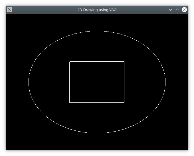
Figure 11: 2D OpenGL draw using VAO - Vertex Array Object
Sample Code
File: CMakeLists.txt
cmake_minimum_required(VERSION 3.5)
project(draw2d)

set(CMAKE_CXX_STANDARD 17)
set(CMAKE_CXX_STANDARD_REQUIRED ON)
set(CMAKE_VERBOSE_MAKEFILE ON)

#================ GLFW Settings  ===============#

find_package(OpenGL REQUIRED)

include(FetchContent)

# Set GLFW Options before FectchContent_MakeAvailable
set( GLFW_BUILD_EXAMPLES OFF CACHE BOOL  "GLFW lib only" )
set( GLFW_BUILD_TESTS    OFF CACHE BOOL  "GLFW lib only" )
set( GLFW_BUILD_DOCS     OFF CACHE BOOL  "GLFW lib only" )
set( GLFW_BUILD_INSTALL  OFF CACHE BOOL  "GLFW lib only" )

# Donwload GLFW library
FetchContent_Declare(
  glfwlib
  URL   https://github.com/glfw/glfw/releases/download/3.3.2/glfw-3.3.2.zip
)
FetchContent_MakeAvailable(glfwlib)

       add_executable( draw2d-vao  draw2d-vao.cpp )
target_link_libraries( draw2d-vao  glfw OpenGL::GL GLU)
File: draw2d-vao.cpp
// Draw curve mapping buffer to the GPU.
#include <iostream>
#include <vector>
#include <array>
#include <cmath>
#include <cassert>

// -------- OpenGL headers ---------//
//
#define GL_GLEXT_PROTOTYPES 1 // Necessary for OpenGL >= 3.0 functions
#define GL3_PROTOTYPES      1 // Necessary for OpenGL >= 3.0 functions

#include <GL/gl.h>
#include <GLFW/glfw3.h>

// #include <GL/glew.h>
#include <GL/glu.h>
#include <GL/glut.h>


struct Vertex2D
{
    GLfloat x;
    GLfloat y;
};

// Upload buffer from main memory to GPU VBO
// =>> Parameters VAO, VBO are allocated by the caller.
void send_buffer(   GLuint* pVao        // Pointer to VAO (Vertex Array Object) - allocated by caller
                  , GLuint* pVbo        // Pointer to VBO (Vertex Buffer Object) - allocated by caller
                  , GLsizei sizeBuffer  // Total buffer size in bytes
                  , void*   pBufffer    // Pointer to buffer
                  , GLint   shader_attr // Shader attribute location
                  , GLint   size        // Number of coordinates of a given vertex
                  , GLenum  type        // Type of each element coordinate
                  );

void* map_buffer( GLuint* pVao         // Pointer to VAO - allocated by calling code.
                , GLuint* pVbo         // Pointer to VBO - allocated by calling code.
                , GLsizei data_size    // Total size in bytes that is allocated to buffer
                , GLint   shader_attr  // Shadder attribute location id (0 - zero) is there is no shader.
                , GLint   size         // Number of component of each vertex
                , GLenum  type         // Type of each vertex element
                );


int main(int argc, char** argv)
{
    GLFWwindow* window;

    /* Initialize the library */
    if (!glfwInit())
        return -1;

    glutInit(&argc, argv);

    /* Create a windowed mode window and its OpenGL context */
    window = glfwCreateWindow(640, 480, "2D Drawing using VAO", NULL, NULL);
    if (!window)
    {
        glfwTerminate();
        return -1;
    }

    /* Make the window's context current */
    glfwMakeContextCurrent(window);
    // glClearColor(0.0f, 0.5f, 0.6f, 1.0f);
    glClearColor(0.0f, 0.0f, 0.0, 1.0f);

    // Shader attribute location (default 0)
    GLint shader_attr = 0;


    // ================ Square / Vertex Buffer Object 2 ==================//
    //

    Vertex2D square_points[4] = {
        { -0.3,  -0.3 }
      , { -0.3,   0.3 }
      , {  0.3,   0.3 }
      , {  0.3,  -0.3 }
    };

    GLuint vao_square = 0;
    GLuint vbo_square = 0;

    // Upload square_points buffer data to GPU
    send_buffer( &vao_square, &vbo_square, sizeof(square_points)
                , square_points, shader_attr, 2, GL_FLOAT );

    assert( vao_square != 0 );
    assert( vbo_square != 0 );

    std::fprintf( stderr, " [TRACE] vao_square = %d, vbo_square = %d \n"
                 , vao_square, vbo_square);


    // ============== Circle / Vertex Buffer Object 3 ==================//
    //
    GLuint vao_circle = 0;
    GLuint vbo_circle = 0;

    // Number of vertices to used to render the circle.
    constexpr size_t N_CIRCLE = 100;
    constexpr float  PI       = 3.1415927;
    const     float  radius   = 0.75;

    // C-style cast should not be used here
    Vertex2D* pCursor = (Vertex2D*) map_buffer( &vao_circle, &vbo_circle, N_CIRCLE * sizeof(Vertex2D)
                                              , shader_attr, 2, GL_FLOAT );

    float angle = 0.0;
    const float step = 2 * PI / N_CIRCLE;

    for(size_t n = 0; n < N_CIRCLE; n++)
    {
        pCursor[n].x = radius * cosf( angle );
        pCursor[n].y = radius * sinf( angle );
        angle = angle + step;
    }


    //  ======= R E N D E R  - L O O P ============//
    //                                             //
    while ( !glfwWindowShouldClose(window) )
    {
        glClear(GL_COLOR_BUFFER_BIT);

        // ====== BEGIN RENDERING ============//

            //------------ Draw Square -------------------------//
            //
             glBindVertexArray(vao_square);
            // Plot 4 vertices
            glDrawArrays(GL_LINE_LOOP, 0, 4);
            // Unbind vao (restore global state to default value)
            glBindVertexArray(0);

            //------------ Draw Circle -------------------------//
            //
            glBindVertexArray(vao_circle);
            glDrawArrays(GL_LINE_LOOP, 0, N_CIRCLE);
            glBindVertexArray(0);

        // ====== END RENDERING ==============//

        /* Swap front and back buffers */
        glfwSwapBuffers(window);
        /* Poll for and process events */
        glfwPollEvents();

        if( glfwGetKey(window, 'Q' ) == GLFW_PRESS )
        {
             std::cout << " [TRACE] User typed Q =>> Shutdown program. Ok. " << '\n';
             break;
        }
    }

    // ---------- Dispose Buffer Objects ---------//
    glDeleteBuffers(1, &vbo_square);
    glDeleteBuffers(1, &vbo_circle);

    glfwTerminate();
    return 0;
}

// ---------- I M P L E M E N T A T I O N S ------------------//
//                                                            //

// Upload buffer from main memory to GPU VBO
// =>> Parameters VAO, VBO are allocated by the caller.
void send_buffer(   GLuint* pVao        // Pointer to VAO (Vertex Array Object) - allocated by caller
                  , GLuint* pVbo        // Pointer to VBO (Vertex Buffer Object) - allocated by caller
                  , GLsizei sizeBuffer  // Total buffer size in bytes
                  , void*   pBufffer    // Pointer to buffer
                  , GLint   shader_attr // Shader attribute location id
                  , GLint   size        // Number of coordinates of a given vertex
                  , GLenum  type        // Type of each element coordinate
                  )
{
    assert(pVao != nullptr);
    assert(pVbo != nullptr);
    GLuint& vao = *pVao;
    GLuint& vbo = *pVbo;

    // Generate and bind current VAO (Vertex Array Object)
    glGenVertexArrays(1, &vao);
    glBindVertexArray(vao);

    // Generate and bind current VBO (Vertex Buffer Object)
    glGenBuffers(1, &vbo);
    glBindBuffer(GL_ARRAY_BUFFER, vbo);

    // Upload data to current VBO buffer in GPU
    glBufferData(GL_ARRAY_BUFFER, sizeBuffer, pBufffer, GL_STATIC_DRAW);

    glEnableVertexAttribArray(shader_attr);

    // Set data layout - how data will be interpreted.
    glVertexAttribPointer(shader_attr, size, type, GL_FALSE, 0, nullptr);

    // ------ Disable Global state set by this function -----//
    //
    // Unbind VAO
    glBindVertexArray(0);
    // Unbind VBO
    glBindBuffer(GL_ARRAY_BUFFER, vbo);
    // Disable current shader attribute
    glDisableVertexAttribArray(shader_attr);

}

void* map_buffer( GLuint* pVao         // Pointer to VAO - allocated by calling code.
                , GLuint* pVbo         // Pointer to VBO - allocated by calling code.
                , GLsizei data_size    // Total size in bytes that is allocated to buffer
                , GLint   shader_attr  // Shadder attribute location id (0 - zero) is there is no shader.
                , GLint   size         // Number of component of each vertex
                , GLenum  type         // Type of each vertex element
                )
{
    GLuint& vao = *pVao;
    GLuint& vbo = *pVbo;

    // Generate and bind current VAO (Vertex Array Object)
    glGenVertexArrays(1, &vao);
    glBindVertexArray(vao);

    // Generate and bind current VBO (Vertex Buffer Object)
    glGenBuffers(1, &vbo);
    glBindBuffer(GL_ARRAY_BUFFER, vbo);

    /** See: https://www.khronos.org/registry/OpenGL-Refpages/gl4/html/glMapBuffer.xhtml
     *  Khronos Group: "glMapBuffer and glMapNamedBuffer map the entire data store of
     *  a specified buffer object into the client's address space. The data can then be directly
     *  read and/or written relative to the returned pointer,
     *  depending on the specified access policy."
     */
    glBufferData(GL_ARRAY_BUFFER, data_size, nullptr, GL_STATIC_DRAW);
    void* pbuffer = glMapBuffer( GL_ARRAY_BUFFER, GL_WRITE_ONLY );

    glEnableVertexAttribArray(shader_attr);
    // Set data layout - how data will be interpreted.
    glVertexAttribPointer(shader_attr, size, type, GL_FALSE, 0, nullptr);

    // ------ Disable Global state set by this function -----//
    //
    // Unbind VAO
    glBindVertexArray(0);
    // Unbind VBO
    glBindBuffer(GL_ARRAY_BUFFER, vbo);
    // Disable current shader attribute
    glDisableVertexAttribArray(shader_attr);

    // ------- Return --------------------------------------//
    return pbuffer;
}
1.19 2D - using shaders
OpenGL retained mode (programmable pipeline) uses shaders, which are programs that uses GLSL (OpenGL shading language) programming language, runs on the GPU (Graphics Processing Unit). A vertex shader performs vertex coordinate transformations on all vertices and colors received from VBO - Vertex Buffer Objects. The fragment shader runs after the vertex shader and deals with vertice texture and color computations.
A vertex shader has the following features:
- Data types:
- float => Float IEEE754 32 bits floating point scalar.
- vec2 => Vector of 2 coordinates
- vec3 => Vector of 3 coordinates
- vec4 => Vector of 4 coordinates
- mat2 => 2x2 matrix
- mat4 => 4x4 homogeneous coordinate matrix
- mat3 => 3x3 matrix
- uniform variables => Shader variables declared with uniform storage
qualifier. They allow passing data, such as transformation
matrices, vectors or scalar values, from the C++-side to the shader
program. Uniform variables can be used for passing the model matrix,
camera matrix and projection matrix to the shader.
- Declaration example: 'uniform mat4 u_model;'
- attribute variables => Used for passing vertices or color
coordinates from VBOs (Vertex Buffer Objects). Those variables are
only accessible in the shader.
- Declaration example: 'layout ( location = 2) in vec2 position;'
- Output => Shader programs uses pre-defined global variables for output, for instance, gl_Position, which sets the current vertex position in clip-space (NDC - Normalized Device Coordinates).
Documentation
- Core Language (GLSL) - OpenGL Wiki / Khronos Group.
- Syntax of GLSL (OpenGL shading language)
- Data Type (GLSL) - OpenGL Wiki / Khronos Group
- OpenGL Shading Language - Wikipedia
- Shader - OpenGL Wiki / Khronos Group
- Vertex Shader - OpenGL Wiki / Khronos Group
- Fragment Shader - OpenGL Wiki / Khronos Group
- Uniform (GLSL) - OpenGL Wiki / Khronos Group
- Discusses shader uniform variables.
- Layout Qualifier (GLSL) - OpenGL Wiki / Khronos Group
- Shader attribute index (attribute location)
- Geometry Shader - OpenGL Wiki / Khronos Group.
- Shader Compilation - OpenGL Wiki / Khronos Group.
- Vertex Rendering - OpenGL Wiki
- Data in WebGL - Web APIs | MDN / Mozilla
- Explanation of shader's attribute variables and shader's uniform variables.
Source Code
Summary:
- This sample application, draws many 4 triangles from a 2 VBO (Vertex Buffer Object) and a single VAO (Vertex Array Object). The application uses a vertex shader for performing coordinate transformation for every triangle and drawing them at different position with different rotation angles around Z axis. The triangle 'triangleD' follows the mouse position while the triangle 'triangleB' rotates acoording to the mouse position.
- The vertex shader has two attributes variables ('position' and 'color') and two uniform variables u_model, that contains the model matrix from every rendered object, and u_projection, which contains the projection matrix.
Screenshot:
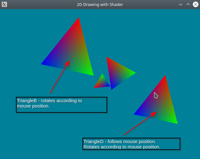
Vertex Shader - Source Code (Extraced from draw2d-shader.cpp)
#version 330 core

// Supplied by GPU - attribute location (id = 2)
// contains a (X, Y) vertex
layout ( location = 2)  in vec2 position;
layout ( location = 1 ) in vec3 color;     // Contains (Red, Green, Blue) components

// Output to fragment shader
out vec3 out_color;

// Model matrix => projection coordinates from the local space (model space)
// to view space .
// Transform 4x4 matrix - supplied by the C++ side.
uniform mat4 u_model;

// Projection matrix => projections camera-space coordinates
// to clip-space coordinates. (-1.0 to 1.0) range.
uniform mat4 u_projection;

void main()
{
    // gl_Position => Global output variable that holds the
    // the current vertex position. It is a vector of
    // components (X, Y, Z = 0, W = ignored)
    gl_Position = u_projection * u_model * vec4(position, 0, 1.0);

    // Forward to fragment shader
    out_color = color;
}
Fragment Shader - Source Code (Extracted from draw2d-shader.cpp)
#version 330

// This color comes from Vertex shader
in vec3 out_color;

void main()
{
    // Set vertex colors
    gl_FragColor = vec4(out_color, 1.0);

}
File: CMakeLists.txt
cmake_minimum_required(VERSION 3.5)
project(GLFW_project)

set(CMAKE_CXX_STANDARD 17)
set(CMAKE_CXX_STANDARD_REQUIRED ON)
set(CMAKE_VERBOSE_MAKEFILE ON)

#================ GLFW Settings  ===============#

find_package(OpenGL REQUIRED)

include(FetchContent)

# Set GLFW Options before FectchContent_MakeAvailable
set( GLFW_BUILD_EXAMPLES OFF CACHE BOOL  "GLFW lib only" )
set( GLFW_BUILD_TESTS    OFF CACHE BOOL  "GLFW lib only" )
set( GLFW_BUILD_DOCS     OFF CACHE BOOL  "GLFW lib only" )
set( GLFW_BUILD_INSTALL  OFF CACHE BOOL  "GLFW lib only" )

# Donwload GLFW library
FetchContent_Declare(
  glfwlib
  URL   https://github.com/glfw/glfw/releases/download/3.3.2/glfw-3.3.2.zip
)
FetchContent_MakeAvailable(glfwlib)

# Download GLM (OpenGL math library for matrix and vectors transformation)
FetchContent_Declare(
  glm
  URL  https://github.com/g-truc/glm/archive/0.9.8.zip
)
FetchContent_MakeAvailable(glm)

message( [DEBUG] " glm_SOURCE_DIR = ${glm_SOURCE_DIR} ")
include_directories(${glm_SOURCE_DIR})

  # ======= TARGETS ===========================#

       add_executable( draw2d-shader  draw2d-shader.cpp   )
target_link_libraries( draw2d-shader  glfw OpenGL::GL GLU )
File: draw2d-shader.cpp
// Draw many colored triangles from a single VBO (Vertex Buffer Object)
#include <iostream>
#include <vector>
#include <array>
#include <cmath>
#include <functional>

// -------- OpenGL headers ---------//
//
#define GL_GLEXT_PROTOTYPES 1 // Necessary for OpenGL >= 3.0 functions
#define GL3_PROTOTYPES      1 // Necessary for OpenGL >= 3.0 functions

#include <GL/gl.h>
#include <GLFW/glfw3.h>

// #include <GL/glew.h>
#include <GL/glu.h>

// --------- OpenGL Math Librar ------------//
#include <glm/glm.hpp>
#include <glm/gtc/matrix_transform.hpp>
#include <glm/gtc/type_ptr.hpp>
#include <glm/gtx/string_cast.hpp>


// Compile some  shader
void compile_shader(GLuint m_program, const char* code, GLenum type);

// Send data from memory to GPU VBO memory
void send_buffer(   GLuint* pVao        // Pointer to VAO (Vertex Array Object) - allocated by caller
                  , GLuint* pVbo        // Pointer to VBO (Vertex Buffer Object) - allocated by caller
                  , GLsizei sizeBuffer  // Total buffer size in bytes
                  , void*   pBufffer    // Pointer to buffer
                  , GLint   shader_attr // Shader attribute location id
                  , GLint   size        // Number of coordinates of a given vertex
                  , GLenum  type        // Type of each element coordinate
                  );

// ------------ Basic Data Structures -----------//

// Wrapper for 2D vertex coordinates
struct Vertex2D{  GLfloat x, y;  };
// Wrapper for RGB colors
struct ColorRGB { GLfloat r, g, b; };

constexpr ColorRGB COLOR_R = { 1.0, 0.0, 0.0  }; // Red
constexpr ColorRGB COLOR_G = { 0.0, 1.0, 0.0  }; // Green
constexpr ColorRGB COLOR_B = { 0.0, 0.0, 1.0  }; // Blue


class Model_Triangle
{
    // Object position in World Coordinates
    float _x = 0.0, _y = 0.0;
    // Scale
    float _scale = 1.0;
    // Rotation angle around z axis
    float _angle = 0.0;

public:
    Model_Triangle(float scale = 1.0){   }
    void rotate(float angle)          { _angle = angle; }
    void translate(float x , float y) { _x = x; _y = y; }
    void scale(float scale)           { _scale = scale; }
    void zoom(float factor)           {  _scale = factor + _scale; }

    // Render/draw this object
    void render(GLuint vao, GLint  u_model)
    {

        // Reset model matrix to indentiy matrix
        glm::mat4 _model(1.0);
        // Scale object (increase or decrease object size)
        _model =  glm::scale( _model, glm::vec3(_scale, _scale, _scale) );
        // Move to (X, Y) position
        _model = glm::translate( _model, glm::vec3(_x, _y, 0.0)  );
        // Rotate from a given angle around Z axis at current object X, Y  postion
        _model = glm::rotate( _model, glm::radians(_angle), glm::vec3(0, 0, 1) );

        // Set shader uniform variable.
        glUniformMatrix4fv(
            // Shader uniform variable location
            u_model
            // Number of matrices that will be set
            , 1
            // GL_FALSE => Matrix is in column-major order (Fortran matrix layout)
            // GL_TRUE  => Matrix is in row-major order (C, C++ array, matrix layout)
            , GL_FALSE
            // Pointer to first element transform matrix (homogeneous coordinate)
            , glm::value_ptr(_model)
        );
        glBindVertexArray(vao);
        // Draw 3 vertices
        glDrawArrays(GL_TRIANGLES, 0, 3);
        // Disable global state
        glBindVertexArray(0);
    }
};


// Global variable [WARNING] - Vulnerable to global "initialization fiasco"
// undefined behavior.
auto Cursor_Callback = std::function<void (GLFWwindow* window, double xpos, double ypos)>();

int main(int argc, char** argv)
{

    /* Initialize the library */
    if (!glfwInit()){ return -1; }

    // OpenGL Core Profile
    glfwWindowHint(GLFW_CONTEXT_VERSION_MAJOR, 3);
    glfwWindowHint(GLFW_CONTEXT_VERSION_MINOR, 3);
    glfwWindowHint(GLFW_OPENGL_PROFILE, GLFW_OPENGL_CORE_PROFILE);

    glfwSetErrorCallback([](int error, const char* description)
                         {
                            std::cerr << " [GLFW ERROR] " << error
                                      << ": " << description
                                      << std::endl;
                         });

    GLFWwindow* window = glfwCreateWindow(640, 480, "2D Drawing with Shader", NULL, NULL);
    if (!window){ glfwTerminate(); return -1; }

    // OpenGL context
    glfwMakeContextCurrent(window);
    glClearColor(0.0f, 0.5f, 0.6f, 1.0f);

    // Mouse move callback
    // Note: It is only possible to pass non-capturing lambda to this callback.
    glfwSetCursorPosCallback( window
                            , [](GLFWwindow* window, double xpos, double ypos)
                              {
                                  // Forward call to global variable std::function<>
                                  // (Function object)
                                  Cursor_Callback(window, xpos, ypos);
                              });

    // ====== S H A D E R - C O M P I L A T I O N ====//
    //                                                //

    // Note: The shader source code is at the end of file.
    extern const char* code_vertex_shader;
    extern const char* code_frag_shader;

    GLuint prog = glCreateProgram();
    // Compile shader code
    compile_shader(prog, code_vertex_shader, GL_VERTEX_SHADER  ) ;
    compile_shader(prog, code_frag_shader,   GL_FRAGMENT_SHADER );

    // Bind current shader (enable it). Only one shader of the same type can
    // be bound at a time. For instance, only a single vertex shader can
    // be enabled at a time
    glUseProgram(prog);

    // Get shader uniform variable location for projection matrix
    // See shader code: "uniform mat4 projection;"
    const GLint u_proj  = glGetUniformLocation(prog, "u_projection");
    assert( u_proj >= 0 && "Failed to find uniform variable" );

    // Get shader uniform variable  location for model matrix.
    const GLint u_model  = glGetUniformLocation(prog, "u_model");
    assert( u_model >= 0 && "Failed to find uniform variable" );

    // Get shader attribute location - the function glGetAttribLocation - returns (-1) on error.
    const GLint attr_position = glGetAttribLocation(prog, "position");
    assert( attr_position >= 0 && "Failed to get attribute location" );
    std::fprintf(stderr, " [TRACE] Attribute location attr_position = %d \n"
                , attr_position);

    // Get shader index of color attribute variable.
    const GLint attr_color = glGetAttribLocation(prog, "color");
    assert( attr_color >= 0);


    // ====== U P L O A D - TO - G P U =========================//
    //                                                          //

    constexpr size_t NUM_VERTICES = 3;

    // Array of triangle vertex coordinates (X, Y)
    Vertex2D vertices[NUM_VERTICES] = {
      {  0.0,   0.2} // Vertex 0  (x =  0.0 ; y =  0.5)
    , { -0.2,  -0.2} // Vertex 1  (x = -0.5 ; y = -0.5)
    , {  0.2,  -0.2} // Vertex 2  (x =  0.5 ; y = -0.5)
    };

    ColorRGB colors[NUM_VERTICES] = {
          COLOR_R   // Color of vertex 0
        , COLOR_B   // Color of vertex 1
        , COLOR_G   // Color of vertex 2
    };

    // Always initialize with zero (0), otherwise, the values
    // of those variables will be undefined. (Undefine Behavior)
    GLuint vao_triangle = 0;
    GLuint vbo_vertices = 0;
    GLuint vbo_colors   = 0;

    // Send vertices to GPU VBO (vbo_vertices)
    send_buffer(  &vao_triangle    // Ponter to VAO [OUTPUT]
                , &vbo_vertices    // Pointer VBO   [OUTPUT]
                , sizeof(vertices) // Size of buffer sent to GPU (VBO memory)
                , vertices         // Pointer to buffer
                , attr_position    // Shader attribute location
                , 2                // Each vertex has 2 coordinates (X, Y)
                , GL_FLOAT         // Each vertex coordinate has type GLfloat (float)
                );

    // Send colors to GPU VBO (vbo_colors)
    send_buffer(  &vao_triangle   // Pointer Vertex Array object
                , &vbo_colors     // Pointer Vertex buffer object handle (aka token)
                , sizeof(colors)  // Buffer size
                , colors          // Pointer to buffer (addrress of first buffer element)
                , attr_color      // Shader attribute location
                , 3               // Each color has 3 coordinates (R, G, B)
                , GL_FLOAT        // Each color coordiante has type GLfloat
                );

    // ============== Set Shader Uniform Variables =============//
    //                                                          //

    int width, height;
    glfwGetWindowSize(window, &width, &height);

    // Window aspect ratio
    float aspect = static_cast<float>(width) / height;

    // Identity matrix
    const auto identity = glm::mat4(1.0);

    // Projection matrix - orthogonal projection for compensating
    // the aspect ratio.
    glm::mat4 Tproj = glm::ortho(-aspect, aspect, -1.0f, 1.0f, -1.0f, 1.0f);

    // Set projection matrix uniform variable
    glUniformMatrix4fv(u_proj, 1, GL_FALSE, glm::value_ptr(Tproj) );
    // Set model matrix uniform variable
    glUniformMatrix4fv(u_model, 1, GL_FALSE, glm::value_ptr(identity) );

    // Instatiate objects that will be rendered
    auto triangleA = Model_Triangle{};
    triangleA.scale(0.50);
    triangleA.rotate(122);

    auto triangleB = Model_Triangle{};
    triangleB.translate(-0.20, 0.30);
    triangleB.rotate(50);
    triangleB.scale(1.8);

    auto triangleC = Model_Triangle{};
    triangleC.translate(0.20, 0.20);
    triangleC.rotate(35);

    // Follows mouse coordinate
    auto triangleD = Model_Triangle{};
    triangleD.translate(-0.60, -0.50);
    triangleD.scale(1.50);
    // triangleD.scale(1.2);
    // triangleD.rotate(40);

    // --------- Set mouse callback ----------//

    constexpr float PI = 3.1415926536f;
    constexpr float FACTOR_RAD_TO_DEG = 180.0 / PI;

    Cursor_Callback = [&](GLFWwindow* window, double xpos, double ypos)
    {
        // Mouse normalized coordinate
        // =>> see: https://stackoverflow.com/questions/23870750/
        float xMouse = -1.0f + 2.0f * xpos / width;
        float yMouse =  1.0f - 2.0f * ypos / height;

        // Angle in degrees between X axis vector(1, 0, 0) and poit (xMouse, yMouse, 0) position.
        // Note: atan2f() returns angle in radians.
        float angle = atan2f(yMouse, xMouse) * FACTOR_RAD_TO_DEG ;
        fprintf(stderr, " [TRACE] Angle = %f \n", angle);

        // Triangle D follows mouse position
        triangleD.translate(xMouse, yMouse);
        triangleD.rotate(angle);

        triangleB.rotate(angle);

        // Show mouse position
         // std::fprintf(stderr, " [MOUSE] x = %f ; y = %f \n", xMouse, yMouse);
    };

    //  ======= R E N D E R  - L O O P ============//
    //                                             //
    while ( !glfwWindowShouldClose(window) )
    {
        glClear(GL_COLOR_BUFFER_BIT);

        // ====== BEGIN RENDERING ============//

            triangleA.render(vao_triangle, u_model);
            triangleB.render(vao_triangle, u_model);
            triangleC.render(vao_triangle, u_model);
            triangleD.render(vao_triangle, u_model);

            //std::fprintf(stderr, " [TRACE] Redraw screen \n");

        // ====== END RENDERING ==============//

        /* Swap front and back buffers */
        glfwSwapBuffers(window);
        /* Poll for and process events */
        glfwPollEvents();

        if( glfwGetKey(window, 'Q' ) == GLFW_PRESS )
        {
             std::cout << " [TRACE] User typed Q =>> Shutdown program. Ok. " << '\n';
             break;
        }

        // Increase scale by 10%
        if( glfwGetKey(window, 'A' ) == GLFW_PRESS ){ triangleD.zoom(+0.10); }
        // Decrease scale by 10%
        if( glfwGetKey(window, 'B' ) == GLFW_PRESS ){ triangleD.zoom(-0.10); }


    }

    glfwTerminate();
    return 0;

} // --- End of main() -----//


// Minimal vertex shader =>> Runs on the GPU and processes each vertex.
const char* code_vertex_shader = R"(
    #version 330 core

    // Supplied by GPU - attribute location (id = 2)
    // contains a (X, Y) vertex
    layout ( location = 2)  in vec2 position;
    layout ( location = 1 ) in vec3 color;     // Contains (Red, Green, Blue) components

    // Output to fragment shader
    out vec3 out_color;

    // Model matrix => projection coordinates from the local space (model space)
    // to view space .
    // Transform 4x4 matrix - supplied by the C++ side.
    uniform mat4 u_model;

    // Projection matrix => projections camera-space coordinates
    // to clip-space coordinates. (-1.0 to 1.0) range.
    uniform mat4 u_projection;

    void main()
    {
        // gl_Position => Global output variable that holds the
        // the current vertex position. It is a vector of
        // components (X, Y, Z = 0, W = ignored)
        gl_Position = u_projection * u_model * vec4(position, 0, 1.0);

        // Forward to fragment shader
        out_color = color;
    }

)";

// Fragment shader source code
const char* code_frag_shader = R"(
    #version 330

    // This color comes from Vertex shader
    in vec3 out_color;

    void main()
    {
        // Set vertex colors
        gl_FragColor = vec4(out_color, 1.0);

    }
)";

    // ====== I M P L E M E N T A T I O N S ==========//

void compile_shader(GLuint m_program, const char* code, GLenum type)
{
    GLint shader_id = glCreateShader( type );
    glShaderSource(shader_id, 1, &code, nullptr);
    glCompileShader(shader_id);

    GLint is_compiled = GL_FALSE;
    // Check shader compilation result
    glGetShaderiv(shader_id, GL_COMPILE_STATUS, &is_compiled);

    // If there is any shader compilation result,
    // print the error message.
    if( is_compiled == GL_FALSE)
    {
        GLint length;
        glGetShaderiv(shader_id, GL_INFO_LOG_LENGTH, &length);
        assert( length > 0 );

        std::string out(length + 1, 0x00);
        GLint chars_written;
        glGetShaderInfoLog(shader_id, length, &chars_written, out.data());
        std::cerr << " [SHADER ERROR] = " << out << '\n';
        // Abort the exection of current process.
        std::abort();
    }

    glAttachShader(m_program, shader_id);
    glDeleteShader(shader_id);
    glLinkProgram(m_program);
    GLint link_status = GL_FALSE;
    glGetProgramiv(m_program, GL_LINK_STATUS, &link_status);
    assert( link_status != GL_FALSE );
    // glUseProgram(m_program);
}

// Upload buffer from main memory to GPU VBO
// =>> Parameters VAO, VBO are allocated by the caller.
void send_buffer( GLuint* pVao, GLuint* pVbo, GLsizei sizeBuffer
                , void* pBufffer, GLint   shader_attr, GLint size
                , GLenum type)
{
    assert(pVao != nullptr);
    assert(pVbo != nullptr);
    GLuint& vao = *pVao;
    GLuint& vbo = *pVbo;

    // Generate and bind current VAO (Vertex Array Object)
    if(vao == 0){ glGenVertexArrays(1, &vao); }
    glBindVertexArray(vao);

    // Generate and bind current VBO (Vertex Buffer Object)
    glGenBuffers(1, &vbo);
    glBindBuffer(GL_ARRAY_BUFFER, vbo);

    // Upload data to current VBO buffer in GPU
    glBufferData(GL_ARRAY_BUFFER, sizeBuffer, pBufffer, GL_STATIC_DRAW);

    glEnableVertexAttribArray(shader_attr);

    // Set data layout - how data will be interpreted.
    glVertexAttribPointer(shader_attr, size, type, GL_FALSE, 0, nullptr);

    // ------ Disable Global state set by this function -----//
    //
    // Unbind VAO
    glBindVertexArray(0);
    // Unbind VBO
    glBindBuffer(GL_ARRAY_BUFFER, vbo);
    // Disable current shader attribute
    glDisableVertexAttribArray(shader_attr);

}
1.20 2D - Chart with orthographic projection
This sample applications draws a 2D chart by plotting two curves, the functions f(x) and g(x). It is possible to adjust the range displayed by the chart by setting xmin, xmax, ymin and ymax using the console. By typing 'A' the chart is displayed adjusting the xmax or ymax for preserving the aspect ratio. By typing 'B' the chart does not preserve the aspect ratio and shows the full range xmin to xmax on the X axis, and ymin to ymax on the Y axis.
- f(x) = 100.0 - x^2
- g(x) = 50 * sin(x / (2 * PI)) + 10
The significant features on this sample code are:
- Orthographic projection transform which allows drawing using user-defined coordinates (world-space coordinates), instead of NDC normalized-device coordinates with range -1.0 to 1.0 on each axis.
- Sending interleaved vertex attributes, namely, positions and colors, to GPU with a single call to glBufferData() and a single VBO - Vertex Buffer Object.
- Usage of threads for allowing the user controlling the displayed range by typing in the console (command line).
Projection matrix
The orthogonal projection matrix is used for allowing user-defined coordinates instead of normalized coordinates in the range -1.0 to 1.0 on for each axis. The orthogonal matrix without aspect-ratio compensation is generated by using the following call to glm::ortho.
glm::mat4 proj = ortho(xmin, xmax, ymin, ymax, zNear = +1.0, zFar = -1.0);
Algorithm for avoiding chart distortion
Consider the following rations \(u_x\) and \(u_y\):
\begin{eqnarray*} u_x &=& \frac{w}{\Delta_x} = \frac{ w }{ x_{max} - x_{min} } \\ u_y &=& \frac{h}{\Delta_y} = \frac{ h }{ y_{max} - y_{min} } \\ \end{eqnarray*}Where:
- w - screen width in pixels.
- h - screen height in pixels.
- \(\Delta_x\) screen width in world-space coordinates.
- \(\Delta_y\) screen height in world-space coordinates.
- \(u_y\) - The ratio \(u_x\) represents how many pixels (real screen lenght) each user-defined unit on world-space coordinate systems represents across the X axis.
- \(u_x\) - The ratio \(u_y\), is similar to \(u_x\), but it is applicable to Y axis.
For instance, if the screen has width of 500 pixels and height of 600 pixels and \(x_{min} = -50\), \(x_{max} = +50\), \(y_{min} = -200\), \(y_{max} = +200\). The ratios \(u_x\) and \(u_y\) will be:
\begin{eqnarray*} \Delta_x &=& x_{max} - x_{min} = 100 \\ \Delta_y &=& y_{max} - y_{min} = 400 \\ u_x &=& \frac{500}{100} = 5 \quad \text{pixels per X axis units} \\ u_y &=& \frac{600}{400} = 1.5 \quad \text{pixels per Y axis units} \\ \end{eqnarray*}The result means that any curve, will appear distorted, for instance a square with side of 10, will be shown on the screen with the width of 10 * ux = 50 pixels and the height of 10 * uy = 10 * 1.5 = 15 pixels. As a result, the square will appear as rectangle. To avoid any distortion, the ratios \(u_x\) and \(u_y\) must be equal, which is expressed as:
\begin{eqnarray*} u_x &=& u_y \\ \frac{x_{max} - x_{min}}{w} &=& \frac{y_{max} - y_{min}}{h} \\ \end{eqnarray*}If the variables w, h, \(x_{min}\) and \(y_{min}\) are fixed. \(x_{max}\) or \(y_{max}\) must be adjusted for making the ratios \(u_x\) and \(u_y\) equal and avoiding any distortion.
If the adjusting is choosen for \(x_{max}\), then its new value will be:
\begin{equation} x_{max}' = x_{min} + \frac{w}{h}( y_{max} - y_{min} ) \end{equation}If the adjusting is choosen for \(y_{max}\), then its adjusted value is:
\begin{equation} y_{max}' = y_{min} + \frac{h}{w}( x_{max} - x_{min} ) \end{equation}By applying the adjusting for the previous case for \(x_{max}\), its adjusted value becomes:
\begin{equation} x_{max}' = (-50) + \frac{500}{600}( 200 - (-200) ) \approx 283.333 \end{equation}The ratios \(u_x\), \(u_y\) become:
\begin{eqnarray*} u_x' &=& \frac{ w }{ x_{max}' - x_{min} } = \frac{ 500 }{ 283.333 - (-50) } \approx 1.50 \\ u_y' &=& \frac{ h }{ y_{max} - y_{min} } = \frac{ 600 }{ 200 - (-200) } = 1.50 \\ \end{eqnarray*}As the ratios became equal, a square of side 10 will not appear distorted as its width and lenght in pixels, became equal.
Screenshots
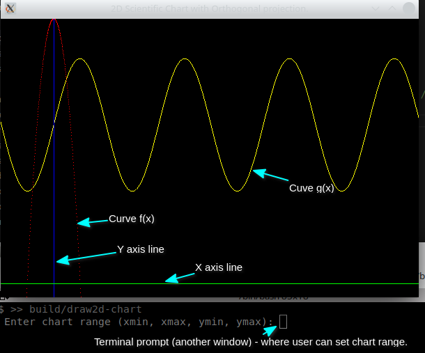
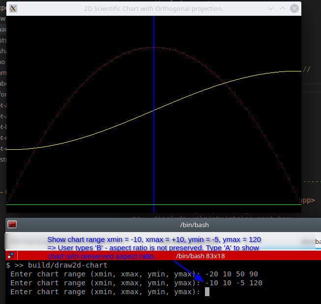
Files and shaders code
Vertex Shader:
#version 330 core

layout ( location = 0) in vec2 position;
layout ( location = 1) in vec3 color;

// Forwarded to fragment shader
out vec3 out_color;

uniform mat4 u_model;  // Model matrix
uniform mat4 u_proj;   // Projection matrix

void main()
{
    // vec4(position, 0.0, 1.0) means => vec4(x, y, z = 0.0, w =1.0)
    gl_Position = u_proj * u_model * vec4(position, 0.0, 1.0);
    // Forward to fragment shader
    out_color = color;
}
Fragment Shader:
#version 330

in vec3 out_color;

void main()
{
    // Set vertex colors
    gl_FragColor =  vec4(out_color, 1.0);
}
File: CMakeLists.txt
cmake_minimum_required(VERSION 3.5)
project(Draw2D-Chart-GLFW)

set(CMAKE_CXX_STANDARD 17)
set(CMAKE_CXX_STANDARD_REQUIRED ON)
set(CMAKE_VERBOSE_MAKEFILE ON)

#================ GLFW Settings  ===============#

find_package(OpenGL REQUIRED)

include(FetchContent)

# Set GLFW Options before FectchContent_MakeAvailable
set( GLFW_BUILD_EXAMPLES OFF CACHE BOOL  "GLFW lib only" )
set( GLFW_BUILD_TESTS    OFF CACHE BOOL  "GLFW lib only" )
set( GLFW_BUILD_DOCS     OFF CACHE BOOL  "GLFW lib only" )
set( GLFW_BUILD_INSTALL  OFF CACHE BOOL  "GLFW lib only" )

# Donwload GLFW library
FetchContent_Declare(
  glfwlib
  URL   https://github.com/glfw/glfw/releases/download/3.3.2/glfw-3.3.2.zip
)
FetchContent_MakeAvailable(glfwlib)

# Download GLM (OpenGL math library for matrix and vectors transformation)
FetchContent_Declare(
  glm
  URL  https://github.com/g-truc/glm/archive/0.9.8.zip
)
FetchContent_MakeAvailable(glm)

message( [DEBUG] " glm_SOURCE_DIR = ${glm_SOURCE_DIR} ")
include_directories(${glm_SOURCE_DIR})

  # ======= TARGETS ===========================#

       add_executable( draw2d-chart  draw2d-chart.cpp   )
target_link_libraries( draw2d-chart  glfw OpenGL::GL GLU )
File: draw2d-chart.cpp
#include <iostream>
#include <vector>
#include <array>
#include <cmath>
#include <cassert>
#include <algorithm>
#include <thread>

// -------- OpenGL headers ---------//
//
#define GL_GLEXT_PROTOTYPES
#define GL3_PROTOTYPES

#include <GL/gl.h>
#include <GLFW/glfw3.h>

// #include <GL/glew.h>
#include <GL/glu.h>
// #include <GL/glut.h>

// --------- OpenGL Math Library ------------//
#include <glm/glm.hpp>
#include <glm/gtc/matrix_transform.hpp>
#include <glm/gtc/type_ptr.hpp>
#include <glm/gtx/string_cast.hpp>
#include <glm/gtc/matrix_access.hpp>

struct Point2D { GLfloat x, y;  };
struct ColorRGB{ GLfloat r, g, b; };

struct Vertex2D
{
    Point2D  position;
    ColorRGB color;
};

constexpr ColorRGB color_red    = { 1.0, 0.0, 0.0 };
constexpr ColorRGB color_green  = { 0.0, 1.0, 0.0 };
constexpr ColorRGB color_blue   = { 0.0, 0.0, 1.0 };
constexpr ColorRGB color_white  = { 1.0, 1.0, 1.0 };
constexpr ColorRGB color_yellow = { 1.0, 1.0, 0.0 };

// ------------------------------------//
// Shader code at the end of file.
extern const char*  code_vertex_shader;
extern const char*  code_frag_shader;

void        compile_shader(GLuint m_program, const char* code, GLenum type);
GLFWwindow* make_glfwWindow(int  width, int height, const char* title);

// Upload vertices position and colors to GPU in a single call.
void send_vertices( GLuint* pVao, GLuint* pVbo
                  , GLint attr_position
                  , GLint attr_color
                  , std::vector<Vertex2D> const& vertices );

// using resize_callback_t = void (*) (GLFWwindow* window, int width, int height);
using FuncResizeCallback = std::function<void (GLFWwindow* window, int width, int height)>;
FuncResizeCallback resize_callback;


/*  Ajust orthogonal projection matrix for keeping the aspect ratio.
 *  If the flag is false, the range (Xmin, Xmax), (Ymax, Ymin) is not adjusted.
 *******************************************************************/
void adjust_window_range( GLFWwindow* window
                        , GLint uniform_projection_id
                        , bool flag
                        , float xmin, float xmax, float ymin, float ymax);


template<typename Function>
auto make_curve(  ColorRGB color, float xmin, float xmax
                , size_t npoints, Function&& fun) -> std::vector<Vertex2D>
{
    std::vector<Vertex2D> curve;
    // Reserve pre-allocated space in order to avoid multiple allocations
    // via vector.push_back(Item)
    curve.reserve(npoints);
    float x = xmin;
    float y = 0.0;
    float dx = (xmax - xmin) / npoints;

    for(size_t n = 0; n < npoints; n++)
    {
        y = fun(x);
        curve.push_back( Vertex2D{ Point2D{x, y}, color } );
        // std::fprintf(stderr, " [TRACE] x = %f ; y = %f \n", x, y);
        x = x + dx;
    }
    return curve;
}

int main()
{
    // Initialize GLFW
    if (!glfwInit()){ return -1; }
    const char* title = "2D Scientific Chart with Orthogonal projection.";
    GLFWwindow* window = make_glfwWindow(600, 400, title);

    // ========== Shader settings ==================//
    //
    GLuint prog = glCreateProgram();
    // Compile shader code
    compile_shader(prog, code_vertex_shader, GL_VERTEX_SHADER  ) ;
    compile_shader(prog, code_frag_shader,   GL_FRAGMENT_SHADER );
    glUseProgram(prog);
    // ------- Shader attribute locations -------//
    //
    const GLint attr_position = glGetAttribLocation(prog, "position");
    const GLint attr_color    = glGetAttribLocation(prog, "color");
    assert( attr_color >= 0 );
    // --------- Shader Uniform Variables -------//
    //
    const GLint u_proj  = glGetUniformLocation(prog, "u_proj");
    const GLint u_model = glGetUniformLocation(prog, "u_model");
    // Note: The error checking for other uniforms are missing
    // for breviety purposes.
    assert( u_model >= 0 );

    // ------ Default values for uniform variables ----------//
    //
    const auto matrix_identity = glm::mat4(1.0);
    glUniformMatrix4fv(u_model, 1, GL_FALSE, glm::value_ptr(matrix_identity));
    glUniformMatrix4fv(u_proj,  1, GL_FALSE, glm::value_ptr(matrix_identity));

    // Forward callback to global variable.
    glfwSetFramebufferSizeCallback(window, [](GLFWwindow* window, int width, int height){
         resize_callback(window, width, height);
    });

     glm::mat4 model_rectangle = glm::mat4(1.0);
    model_rectangle = glm::translate(model_rectangle, glm::vec3(5.0, 4.0, 0.0));

    // ==== O R T H O G O N A L - P R O J E C T I O N =====//
    //
    float xmin = -20.0f, xmax = +10.0f;
    float ymin = -5.0f, ymax  = +100.0f;
    float zNear = +1.0, zFar = -1.0;

    bool aspect_ratio_flag = true;
    adjust_window_range(window, u_proj, aspect_ratio_flag, xmin, xmax, ymin, ymax);

    resize_callback = [&](GLFWwindow* window, int width, int height)
    {
        // std::fprintf(stderr, " [TRACE] Window resize to width = %d ; height = %d \n", width, height);
        // Resize windo view port to the whole window
        glViewport(0, 0, width, height);
    };

    // --- Console loop thread callback =>> Allows user to adjust chart range
    // using console.
    auto console_thread = std::thread( [&]{
        // glfwMakeContextCurrent(window);
        for(;;){
            std::cout << " Enter chart range (xmin, xmax, ymin, ymax): ";
            std::cin >> xmin >> xmax >> ymin >> ymax;
            // Send an empty envent to the render loop for redrawing the window.
            // It makes the subroutine glfwWaitEvents() return to calling code.
            glfwPostEmptyEvent();

        }
    });

    console_thread.detach();

    // ======= U P L O A D - T O - G P U ===========//
    //

#if 1
    // X, Y axis lines at point (0, 0)
    auto chart_axis = std::vector<Vertex2D> {
            // X axis Line - color green
            { { -500.0, 0}, color_green }, { {500.0, 0}, color_green }
            // Y axis Line  - color blue
          , { {0, -500.0}, color_blue },  { {0, 500.0}, color_blue }
    };
    GLuint vao_axis = 0, vbo_axis = 0;
    send_vertices(&vao_axis, &vbo_axis, attr_position, attr_color, chart_axis);
#endif

    auto curve = std::vector<Vertex2D>{};

    GLuint vao_quadratic_curve = 0;
    GLuint vbo_quadratic_curve = 0;
    curve = make_curve( color_red, -20.0, 20.0, 500
                      , [](float x){ return 100.0 - x * x;  });
    GLint quadratic_curve_points = curve.size();
    send_vertices( &vao_quadratic_curve, &vbo_quadratic_curve
                 , attr_position, attr_color, curve );

    // Sine curve f(x) = 25 * sin(x / (2·PI) ) + + 60.0;
    GLuint vao_sine_curve = 0;
    GLuint vbo_sine_curve = 0;
    constexpr float PI_2 = 2.0 * 3.141592653589;
    curve = make_curve(  color_yellow, -50.0, 200.0, 500
                     , [](float x){ return 25.0 * sin(x / PI_2) + 60.0;  } );
    GLint sine_curve_points = curve.size();
    send_vertices( &vao_sine_curve, &vbo_sine_curve
                 , attr_position, attr_color, curve );


    //  ======= R E N D E R  - L O O P ============//
    //                                             //
    while ( !glfwWindowShouldClose(window) )
    {
        glClear(GL_COLOR_BUFFER_BIT  | GL_DEPTH_BUFFER_BIT);

        // ====== BEGIN RENDERING ============//

            // Adjust orthogonal projection and range of coordinates shown in the window.
            adjust_window_range(window, u_proj, aspect_ratio_flag, xmin, xmax, ymin, ymax);

            // Draw lines for X and Y axis
            //-------------------------------//
            glUniformMatrix4fv(u_model, 1, GL_FALSE, glm::value_ptr(matrix_identity));
            glBindVertexArray(vao_axis);
            glDrawArrays(GL_LINES, 0, 4);

            // Draw curve quadratic curve f(x) = 100.0 - x^2
            //-------------------------------//
            glUniformMatrix4fv(u_model, 1, GL_FALSE, glm::value_ptr(matrix_identity));
            glBindVertexArray(vao_quadratic_curve);
            glDrawArrays(GL_POINTS, 0, quadratic_curve_points);

            // Draw sine curve f(x) = 50 * sin(x) + 10.0;
            //-------------------------------//
            glUniformMatrix4fv(u_model, 1, GL_FALSE, glm::value_ptr(matrix_identity));
            glBindVertexArray(vao_sine_curve);
            glDrawArrays(GL_LINE_STRIP, 0, sine_curve_points);


         // ====== END RENDERING ==============//

        // Swap front and back buffers
        glfwSwapBuffers(window);
        // Wait for events - blocks current thread until some event arrives.
        glfwWaitEvents();

        // ====== PROCESS EVENTS =============//

          // std::fprintf(stderr, " [TRACE] Waiting events. \n");

        if( glfwGetKey(window, 'A') == GLFW_PRESS ){  aspect_ratio_flag = true;  }
        if( glfwGetKey(window, 'B') == GLFW_PRESS ){  aspect_ratio_flag = false; }

    } // --- End of render loop --- //

    return 0;
}

// --------- S H A D E R S --------------------------------//

// Minimal vertex shader =>> Runs on the GPU and processes each vertex.
const char* code_vertex_shader = R"(
    #version 330 core

    layout ( location = 0) in vec2 position;
    layout ( location = 1) in vec3 color;

    // Forwarded to fragment shader
    out vec3 out_color;

    uniform mat4 u_model;  // Model matrix
    uniform mat4 u_proj;   // Projection matrix

    void main()
    {
        // vec4(position, 0.0, 1.0) means => vec4(x, y, z = 0.0, w =1.0)
        gl_Position = u_proj * u_model * vec4(position, 0.0, 1.0);
        // Forward to fragment shader
        out_color = color;
    }

)";

// Fragment shader source code
const char* code_frag_shader = R"(
    #version 330

    in vec3 out_color;

    void main()
    {
        // Set vertex colors
        gl_FragColor =  vec4(out_color, 1.0);
    }
)";


// --------- I M P L E M E N T A T I O N S -----------------//

GLFWwindow*
make_glfwWindow(int  width, int height, const char* title)
{

    glfwSetErrorCallback([](int error, const char* description)
                         { std::fprintf( stderr, " [GLFW ERROR] Error = %d ; Description = %s \n"
                                        , error, description);
                         });

    GLFWwindow* window = glfwCreateWindow(width, height, title, NULL, NULL);
    assert( window != nullptr && "Failed  to create Window");

    // OpenGL context
    glfwMakeContextCurrent(window);
    // Pain whole screen as black - dark screen colors are better
    // for avoding eye strain due long hours staring on monitor.
    glClearColor(0.0f, 0.0f, 0.0f, 1.0f);
    // Set - OpenGL Core Profile - version 3.3
    glfwWindowHint(GLFW_CONTEXT_VERSION_MAJOR, 3);
    glfwWindowHint(GLFW_CONTEXT_VERSION_MINOR, 3);
    glfwWindowHint(GLFW_OPENGL_PROFILE, GLFW_OPENGL_CORE_PROFILE);

    // Make the window the topmost (Always on top)
    glfwWindowHint(GLFW_FLOATING, GLFW_TRUE);

    glEnable(GL_COLOR_MATERIAL);
    glEnable(GL_DEPTH_TEST);
    glEnable(GL_BLEND);

    return window;
}


void compile_shader(GLuint m_program, const char* code, GLenum type)
{
    GLint shader_id = glCreateShader( type );
    glShaderSource(shader_id, 1, &code, nullptr);
    glCompileShader(shader_id);

    GLint is_compiled = GL_FALSE;
    // Check shader compilation result
    glGetShaderiv(shader_id, GL_COMPILE_STATUS, &is_compiled);

    // If there is any shader compilation result,
    // print the error message.
    if( is_compiled == GL_FALSE)
    {
        std::cerr << " [SHADER ERROR] =>> Abort execution. " << '\n';
        // Abort the exection of current process.
        std::abort();
    }

    glAttachShader(m_program, shader_id);
    glDeleteShader(shader_id);
    glLinkProgram(m_program);
    GLint link_status = GL_FALSE;
    glGetProgramiv(m_program, GL_LINK_STATUS, &link_status);
    assert( link_status != GL_FALSE );
    // glUseProgram(m_program);
}


// Upload vertices from main memory to GPU memory.
// Vertices position and colors are uploaded in a single call.
void send_vertices( GLuint* pVao, GLuint* pVbo
                  , GLint attr_position
                  , GLint attr_color
                  , std::vector<Vertex2D> const& vertices )
{
    assert(pVao != nullptr);
    assert(pVbo != nullptr);
    GLuint& vao = *pVao;
    GLuint& vbo = *pVbo;
    // Generate and bind current VAO (Vertex Array Object)
    if(vao == 0){ glGenVertexArrays(1, &vao); }
    glBindVertexArray(vao);
    // Generate and bind current VBO (Vertex Buffer Object)
    glGenBuffers(1, &vbo);
    glBindBuffer(GL_ARRAY_BUFFER, vbo);
    // Upload data to current VBO buffer in GPU
    glBufferData(GL_ARRAY_BUFFER, vertices.size() * sizeof(Vertex2D)
                , vertices.data(), GL_STATIC_DRAW);

    glEnableVertexAttribArray(attr_position);
    glEnableVertexAttribArray(attr_color);

    static_assert( sizeof(Vertex2D) == 5 * sizeof(float)
                 ,"Vertex2D size assumption does not hold." );

    static_assert( sizeof(Point2D) == offsetof(Vertex2D, color)
                 , "Invalid offsetof() assumption");

    // Set data layout - how data will be interpreted.
    // => Each vertex has 2 coordinates.
    glVertexAttribPointer( attr_position     // Position vertex shader attribute
                          , 2                // Each position has 2 coordinates (X, Y)
                          , GL_FLOAT         // Type of each coordinate
                          , GL_FALSE
                          , sizeof(Vertex2D) // Offset to next coordinates (5 floats in this case)
                          , nullptr
                          );

    glVertexAttribPointer( attr_color
                           // Each color has 3 components R, G, B
                          , 3
                           // Type of each color coordinate
                          , GL_FLOAT
                          , GL_FALSE
                           // Offset to next coordinates (next row)
                          , sizeof(Vertex2D)
                           // Offset to color member variable in class Vertex2D
                          , reinterpret_cast<void*>( offsetof(Vertex2D, color) )
                          );

    // ------ Disable Global state set by this function -----//
    // Unbind VAO
    glBindVertexArray(0);
    // Unbind VBO
    glBindBuffer(GL_ARRAY_BUFFER, vbo);
    // Disable current shader attribute
    glDisableVertexAttribArray(attr_position);
    glDisableVertexAttribArray(attr_color);
}

void adjust_window_range( GLFWwindow* window
                        , GLint uniform_projection_id
                        , bool flag
                        , float xmin, float xmax, float ymin, float ymax)
{
    constexpr float zFar  = -1.0f;
    constexpr float zNear = +1.0f;

    if(flag == false)
    {
        glm::mat4 proj_1 = glm::ortho(xmin, xmax, ymin, ymax, zNear, zFar);
        glUniformMatrix4fv(uniform_projection_id, 1, GL_FALSE, glm::value_ptr(proj_1));
        return;
    }

    int width, height;
    glfwGetWindowSize(window, &width, &height);
    float k_aspect = static_cast<float>(width) / static_cast<float>(height);
    float dx = xmax - xmin;
    float dy = ymax - ymin;

    if(dx > dy){
        ymax =  ymin + (1.0f / k_aspect ) * dx;
        // std::fprintf(stderr, " [TRACE] Adjust range => ymax = %f \n", ymax);
    } else {
        xmax = xmin + k_aspect * dy;
        // std::fprintf(stderr, " [TRACE] Adjust range => xmax = %f \n", ymax);
    }

    dx = xmax - xmin;
    dy = ymax - ymin;
    float ux = width / dx;
    float uy = height / dy;

    // std::fprintf(stderr, " [TRACE] ux = %f ; uy = %f \n", ux, uy);

    glm::mat4 proj_2 = glm::ortho(xmin, xmax, ymin, ymax, zNear, zFar);
    glUniformMatrix4fv(uniform_projection_id, 1, GL_FALSE, glm::value_ptr(proj_2));
}
1.21 2D - IBO - Index Buffer Object
This code uses OpenGL IBO (Index Buffer Objects) for drawing triangles and lines OpenGL primitives. The IBO is useful for drawing complex objects without repeating vertices, which saves memory and bandwith and increases performance.
Screenshot
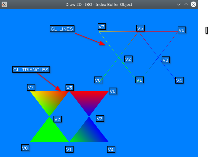
Figure 15: Triangles IBO - Index Buffer Object
Code Highlights
Vertices and colors data structures:
struct Point2D  { GLfloat x, y;    };
struct ColorRGB { GLfloat r, g, b; };
struct Vertex2D { Point2D  position; ColorRGB color; };

using VertexArray = std::vector<Vertex2D>;
using IndexArray  = std::vector<GLuint>;
The next blocks defines the triangles vertices and the connection between those vertices. Each three indices in the 'triangles_indices' variables represents a triangle. Without using IBO (Index Buffer Object), there would be duplicated vertices, then the content of array 'vertices' would be [V0, V1, V2, V1, V3, V4, V3, V5, V6, V2, V7, V5],
// Triangle side
float a = 1.0 / 5.0;
// Triangle height
float h = sqrt(3.0) * a;

auto vertices = VertexArray {
      Vertex2D{ { 0,       0  }, color_green   } // V0 - vertex 0
    , Vertex2D{ { 2 * a,   0  }, color_green   } // V1
    , Vertex2D{ { a,       h  }, color_green   } // V2

    , Vertex2D{ { 3 * a,   h  }, color_blue    } // V3
    , Vertex2D{ { 4 * a,   0  }, color_blue    } // V4

    , Vertex2D{ { 2 * a, 2 * h }, color_red    } // V5
    , Vertex2D{ { 4 * a, 2 * h }, color_red    } // V6
    , Vertex2D{ {     0, 2 * h }, color_yellow } // V7 - vertex 7
};

// Indices for GL_TRIANGLE drawing primitive.
auto triangles_indices = IndexArray {
      0, 1, 2  // Draw triangle with vertices V0, V1, V2 (Triangle A)
    , 1, 3, 4  // Draw triangle with vertices V1, V3, V4 (Triangle B)
    , 3, 5, 6  // Draw triangle with vertices V3, V5, V6 (Triangle C)
    , 2, 7, 5  // Draw triangle with vertices V2, V7, V5 (Triangle D)
};
This index array defines the connections between vertices for GL_LINES primitives, each 2 indices represents a line.
// Indices for GL_LINES drawing primitive
 auto lines_indices = IndexArray {
       0, 1 // Line connecting vertices V0 and V1
     , 0, 2 // Line connecting vertices V0 and V2
     , 1, 2 // Line connecting vertices V1 and V2

     , 2, 7
     , 5, 7
     , 2, 5

     , 1, 3
     , 1, 4
     , 3, 4

     , 3, 5
     , 3, 6
     , 5, 6
 };
In the following code highlight, the vertices indices and data are sent to the GPU using the subroutines send_vertices() and send_indices(). These functions uses the following parameters: vao (Vertex Array Object); vbo (Vertex Buffer Object) and ibo (Index Buffer Objects), which are supposed to be allocated by calling code.
// ------- Upload data for drawing traingle primitives --------//
//
GLuint vao_triangles = 0, vbo_triangles = 0, ibo_triangles = 0;

send_vertices( &vao_triangles, &vbo_triangles
             , attr_position, attr_color, vertices);

send_indices(&vao_triangles, &ibo_triangles, triangles_indices);


// -------- Upload data for drawing lines primitives ----------//
//
GLuint vao_lines = 0, vbo_lines = 0, ibo_lines = 0;
send_vertices( &vao_lines, &vbo_lines
             , attr_position, attr_color, vertices);
send_indices(&vao_lines, &ibo_lines, lines_indices);
At the rendering loop. The OpenGL glDrawElements() subroutine is used ,instead of glDrawArrays(), for drawing triangles and lines primitives. This subroutine uses the vertices indices instead of using the vertices ordering. For instance, if glDrawArrays() was used, each three vertices from the current bound VBO would be used for drawing a triangle.
// ====== BEGIN RENDERING ============//

    // ---- Draw triangles primitives using IBO -------//
    glUniformMatrix4fv(u_model, 1, GL_FALSE, glm::value_ptr(model_triangle_primtives));
    glBindVertexArray(vao_triangles);
    // Draw OpenGL primitives between vertices designated by their
    // IBO - Index Buffer Object.
    glDrawElements(GL_TRIANGLES, triangles_indices.size() , GL_UNSIGNED_INT, nullptr);

    // ----- Draw lines using IBO -----------------------//
    glUniformMatrix4fv(u_model, 1, GL_FALSE, glm::value_ptr(model_lines_primitives));
    glBindVertexArray(vao_lines);
    glDrawElements(GL_LINES, lines_indices.size() , GL_UNSIGNED_INT, nullptr);

// ====== END RENDERING ==============//
Files / Sources
File: CMakeLists.txt
cmake_minimum_required(VERSION 3.5)
project(Draw2D-Chart-GLFW)

set(CMAKE_CXX_STANDARD 17)
set(CMAKE_CXX_STANDARD_REQUIRED ON)
set(CMAKE_VERBOSE_MAKEFILE ON)

#================ GLFW Settings  ===============#

find_package(OpenGL REQUIRED)

include(FetchContent)

# Set GLFW Options before FectchContent_MakeAvailable
set( GLFW_BUILD_EXAMPLES OFF CACHE BOOL  "GLFW lib only" )
set( GLFW_BUILD_TESTS    OFF CACHE BOOL  "GLFW lib only" )
set( GLFW_BUILD_DOCS     OFF CACHE BOOL  "GLFW lib only" )
set( GLFW_BUILD_INSTALL  OFF CACHE BOOL  "GLFW lib only" )

# Donwload GLFW library
FetchContent_Declare(
  glfwlib
  URL   https://github.com/glfw/glfw/releases/download/3.3.2/glfw-3.3.2.zip
)
FetchContent_MakeAvailable(glfwlib)

# Download GLM (OpenGL math library for matrix and vectors transformation)
FetchContent_Declare(
  glm
  URL  https://github.com/g-truc/glm/archive/0.9.8.zip
)
FetchContent_MakeAvailable(glm)

message( [DEBUG] " glm_SOURCE_DIR = ${glm_SOURCE_DIR} ")
include_directories(${glm_SOURCE_DIR})

  # ======= TARGETS ===========================#

       add_executable( draw2d-ibo-triangles  draw2d-ibo-triangles.cpp   )
target_link_libraries( draw2d-ibo-triangles  glfw OpenGL::GL GLU )
File: draw2d-ibo-triangles.cpp
#include <iostream>
#include <vector>
#include <array>
#include <cmath>
#include <cassert>

// -------- OpenGL headers ---------//
//
#define GL_GLEXT_PROTOTYPES 1 // Necessary for OpenGL >= 3.0 functions
#define GL3_PROTOTYPES      1 // Necessary for OpenGL >= 3.0 functions

#include <GL/gl.h>
#include <GLFW/glfw3.h>

#include <GL/gl.h>
#include <GLFW/glfw3.h>

// #include <GL/glew.h>
#include <GL/glu.h>

// --------- OpenGL Math Library ------------//
#include <glm/glm.hpp>
#include <glm/gtc/matrix_transform.hpp>
#include <glm/gtc/type_ptr.hpp>
#include <glm/gtx/string_cast.hpp>
#include <glm/gtc/matrix_access.hpp>

struct Point2D  { GLfloat x, y;    };
struct ColorRGB { GLfloat r, g, b; };
struct Vertex2D { Point2D  position; ColorRGB color; };

extern const char*  code_vertex_shader;
extern const char*  code_frag_shader;

void        compile_shader(GLuint m_program, const char* code, GLenum type);
GLFWwindow* make_glfwWindow(int  width, int height, const char* title);

// Send vertices (position and color of each vertex to GPU memory)
void send_vertices( GLuint* pVao, GLuint* pVbo
                  , GLint attr_position
                  , GLint attr_color
                  , std::vector<Vertex2D> const& vertices );

// Send vertices indices to GPU memory.
void send_indices(GLuint* pVao, GLuint* pVbi
                , std::vector<GLuint> const& indices);

constexpr ColorRGB color_red    = { 1.0, 0.0, 0.0 };
constexpr ColorRGB color_green  = { 0.0, 1.0, 0.0 };
constexpr ColorRGB color_blue   = { 0.0, 0.0, 1.0 };
constexpr ColorRGB color_white  = { 1.0, 1.0, 1.0 };
constexpr ColorRGB color_yellow = { 1.0, 1.0, 0.0 };

int main(int argc, char** argv)
{
    if (!glfwInit()){ return -1; }

    /* Create a windowed mode window and its OpenGL context */
    GLFWwindow* window = make_glfwWindow(640, 480, "Draw 2D - IBO - Index Buffer Object");

    // ======= S H A D E R - C O M P I L A T I O N ==========//
    //
    GLuint prog = glCreateProgram();
    // Compile shader code
    compile_shader(prog, code_vertex_shader, GL_VERTEX_SHADER  ) ;
    compile_shader(prog, code_frag_shader,   GL_FRAGMENT_SHADER );
    glUseProgram(prog);
    // ------- Shader attribute locations -------//
    const GLint attr_position = glGetAttribLocation(prog, "position");
    const GLint attr_color    = glGetAttribLocation(prog, "color");
    assert( attr_position >= 0 );
    assert( attr_color >= 0 );
    // --------- Shader Uniform Variables -------//
    const GLint u_proj  = glGetUniformLocation(prog, "u_proj");
    const GLint u_model = glGetUniformLocation(prog, "u_model");
    assert(u_proj >= 0);
    assert(u_model >= 0);

    // ------ Default values for uniform variables ----------//
    const auto matrix_identity = glm::mat4(1.0);
    glUniformMatrix4fv(u_model, 1, GL_FALSE, glm::value_ptr(matrix_identity));
    glUniformMatrix4fv(u_proj,  1, GL_FALSE, glm::value_ptr(matrix_identity));


    //  ======= U P L O A D - T O - G P U =====================//
    //

    using VertexArray = std::vector<Vertex2D>;
    using IndexArray = std::vector<GLuint>;

    // Triangle side
    float a = 1.0 / 5.0;
    // Triangle height
    float h = sqrt(3.0) * a;

    auto vertices = VertexArray {
          Vertex2D{ { 0,       0  }, color_green   } // V0 - vertex 0
        , Vertex2D{ { 2 * a,   0  }, color_green   } // V1
        , Vertex2D{ { a,       h  }, color_green   } // V2

        , Vertex2D{ { 3 * a,   h  }, color_blue    } // V3
        , Vertex2D{ { 4 * a,   0  }, color_blue    } // V4

        , Vertex2D{ { 2 * a, 2 * h }, color_red    } // V5
        , Vertex2D{ { 4 * a, 2 * h }, color_red    } // V6
        , Vertex2D{ {     0, 2 * h }, color_yellow } // V7 - vertex 7
    };

    // Indices for GL_TRIANGLE drawing primitive.
    auto triangles_indices = IndexArray {
          0, 1, 2  // Draw triangle with vertices V0, V1, V2 (Triangle A)
        , 1, 3, 4  // Draw triangle with vertices V1, V3, V4 (Triangle B)
        , 3, 5, 6  // Draw triangle with vertices V3, V5, V6 (Triangle C)
        , 2, 7, 5  // Draw triangle with vertices V2, V7, V5 (Triangle D)
    };

    // Indices for GL_LINES drawing primitive
    auto lines_indices = IndexArray {
          0, 1 // Line connecting vertices V0 and V1
        , 0, 2 // Line connecting vertices V0 and V2
        , 1, 2 // Line connecting vertices V1 and V2

        , 2, 7
        , 5, 7
        , 2, 5

        , 1, 3
        , 1, 4
        , 3, 4

        , 3, 5
        , 3, 6
        , 5, 6
    };

    // ------- Upload data for drawing traingle primitives --------//
    //
    GLuint vao_triangles = 0, vbo_triangles = 0, ibo_triangles = 0;

    send_vertices( &vao_triangles, &vbo_triangles
                 , attr_position, attr_color, vertices);

    send_indices(&vao_triangles, &ibo_triangles, triangles_indices);


    // -------- Upload data for drawing lines primitives ----------//
    //
    GLuint vao_lines = 0, vbo_lines = 0, ibo_lines = 0;
    send_vertices( &vao_lines, &vbo_lines
                 , attr_position, attr_color, vertices);
    send_indices(&vao_lines, &ibo_lines, lines_indices);

    // ==== Model matrices for translating drawings =======//
    //
    glm::mat4 model_triangle_primtives = matrix_identity;
    glm::mat4 model_lines_primitives = matrix_identity;
    // Translate triangles to point (x = -0.7, y = -0.8, z = 0.0)
    model_triangle_primtives = glm::translate(model_triangle_primtives, glm::vec3(-0.7, -0.8, 0.0));

    //  ======= R E N D E R  - L O O P ===================//
    //                                                    //
    while ( !glfwWindowShouldClose(window) )
    {
        glClear(GL_COLOR_BUFFER_BIT  | GL_DEPTH_BUFFER_BIT);

        // ====== BEGIN RENDERING ============//

            // ---- Draw triangles primitives using IBO -------//
            glUniformMatrix4fv(u_model, 1, GL_FALSE, glm::value_ptr(model_triangle_primtives));
            glBindVertexArray(vao_triangles);
            // Draw OpenGL primitives between vertices designated by their
            // IBO - Index Buffer Object.
            glDrawElements(GL_TRIANGLES, triangles_indices.size() , GL_UNSIGNED_INT, nullptr);

            // ----- Draw lines using IBO -----------------------//
            glUniformMatrix4fv(u_model, 1, GL_FALSE, glm::value_ptr(model_lines_primitives));
            glBindVertexArray(vao_lines);
            glDrawElements(GL_LINES, lines_indices.size() , GL_UNSIGNED_INT, nullptr);

        // ====== END RENDERING ==============//

        glfwSwapBuffers(window);
        glfwPollEvents();
    }

    glfwTerminate();
    return 0;
}

// ---------- S H A D E R S - C O D E  ---------------------//

// Minimal vertex shader =>> Runs on the GPU and processes each vertex.
const char* code_vertex_shader = R"(
    #version 330 core

    layout ( location = 0) in vec2 position;
    layout ( location = 1) in vec3 color;

    // Forwarded to fragment shader
    out vec3 out_color;

    uniform mat4 u_model;  // Model matrix
    uniform mat4 u_proj;   // Projection matrix

    void main()
    {
        // vec4(position, 0.0, 1.0) means => vec4(x, y, z = 0.0, w =1.0)
        gl_Position = u_proj * u_model * vec4(position, 0.0, 1.0);

        // Forward to fragment shader
        out_color = color;
    }

)";

// Fragment shader source code
const char* code_frag_shader = R"(
    #version 330

    in vec3 out_color;

    void main()
    {
        // Set vertex colors
        gl_FragColor =  vec4(out_color, 1.0);
    }
)";

// --------- I M P L E M E N T A T I O N S -----------------//

GLFWwindow*
make_glfwWindow(int  width, int height, const char* title)
{

    glfwSetErrorCallback([](int error, const char* description)
                         { std::fprintf( stderr, " [GLFW ERROR] Error = %d ; Description = %s \n"
                                        , error, description);
                         });

    GLFWwindow* window = glfwCreateWindow(width, height, title, NULL, NULL);
    assert( window != nullptr && "Failed  to create Window");

    // OpenGL context
    glfwMakeContextCurrent(window);
    // Set window color
    glClearColor(0.0f, 0.5f, 3.0f, 1.0f);
    // Set - OpenGL Core Profile - version 3.3
    glfwWindowHint(GLFW_CONTEXT_VERSION_MAJOR, 3);
    glfwWindowHint(GLFW_CONTEXT_VERSION_MINOR, 3);
    glfwWindowHint(GLFW_OPENGL_PROFILE, GLFW_OPENGL_CORE_PROFILE);

    // Make the window the topmost (Always on top)
    glfwWindowHint(GLFW_FLOATING, GLFW_TRUE);

    glEnable(GL_COLOR_MATERIAL);
    glEnable(GL_DEPTH_TEST);
    glEnable(GL_BLEND);

    return window;
}


void compile_shader(GLuint m_program, const char* code, GLenum type)
{
    GLint shader_id = glCreateShader( type );
    glShaderSource(shader_id, 1, &code, nullptr);
    glCompileShader(shader_id);

    GLint is_compiled = GL_FALSE;
    // Check shader compilation result
    glGetShaderiv(shader_id, GL_COMPILE_STATUS, &is_compiled);

    // If there is any shader compilation result,
    // print the error message.
    if( is_compiled == GL_FALSE)
    {
        std::cerr << " [SHADER ERROR] =>> Abort execution. " << '\n';
        // Abort the exection of current process.
        std::abort();
    }

    glAttachShader(m_program, shader_id);
    glDeleteShader(shader_id);
    glLinkProgram(m_program);
    GLint link_status = GL_FALSE;
    glGetProgramiv(m_program, GL_LINK_STATUS, &link_status);
    assert( link_status != GL_FALSE );
    // glUseProgram(m_program);
}

// Upload vertices from main memory to GPU memory.
// Vertices position and colors are uploaded in a single call.
void send_vertices( GLuint* pVao, GLuint* pVbo
                  , GLint attr_position
                  , GLint attr_color
                  , std::vector<Vertex2D> const& vertices )
{
    assert(pVao != nullptr);
    assert(pVbo != nullptr);
    GLuint& vao = *pVao;
    GLuint& vbo = *pVbo;
    // Generate and bind current VAO (Vertex Array Object)
    if(vao == 0){ glGenVertexArrays(1, &vao); }
    glBindVertexArray(vao);
    // Generate and bind current VBO (Vertex Buffer Object)
    glGenBuffers(1, &vbo);
    glBindBuffer(GL_ARRAY_BUFFER, vbo);
    // Upload data to current VBO buffer in GPU
    glBufferData(GL_ARRAY_BUFFER, vertices.size() * sizeof(Vertex2D)
                , vertices.data(), GL_STATIC_DRAW);

    glEnableVertexAttribArray(attr_position);
    glEnableVertexAttribArray(attr_color);

    // Set data layout - how data will be interpreted.
    // => Each vertex has 2 coordinates.
    glVertexAttribPointer( attr_position, 2, GL_FLOAT, GL_FALSE, sizeof(Vertex2D), nullptr);

    glVertexAttribPointer( attr_color, 3, GL_FLOAT, GL_FALSE, sizeof(Vertex2D)
                           // Offset to color member variable in class Vertex2D
                          , reinterpret_cast<void*>( offsetof(Vertex2D, color) )
                          );

    // ------ Disable Global state set by this function -----//
    // Unbind VAO
    glBindVertexArray(0);
    // Unbind VBO
    glBindBuffer(GL_ARRAY_BUFFER, vbo);
    // Disable current shader attribute
    glDisableVertexAttribArray(attr_position);
    glDisableVertexAttribArray(attr_color);
}

void send_indices(GLuint* pVao, GLuint* pVbi, std::vector<GLuint> const& indices)
{
    GLuint& vao = *pVao;
    GLuint& vbi = *pVbi;
    glBindVertexArray(vao);
    // Generate index buffer object
    glGenBuffers(1, &vbi);
    // Bind this index buffer object - only one IBO can
    // be bound at a time. (It is a global state!!)
    glBindBuffer( GL_ELEMENT_ARRAY_BUFFER, vbi );
    // Upload indices to GPU - This VBI object is a handle
    // (token, akin to file descriptor) that refers
    // to the data sent to the GPU on the next line.
    glBufferData( GL_ELEMENT_ARRAY_BUFFER, indices.size() * sizeof(GLuint)
                    , indices.data(), GL_STATIC_DRAW);
    // ----------- Unset global state -------------//
    //
    glBindVertexArray(0);
    glBindBuffer( GL_ELEMENT_ARRAY_BUFFER, 0 );
}
1.22 3D - Rotating cube/box
This sample application contains: two cubes; two grid planes for visual reference; a coordinate axis for visual debugging and a camera that always points to the origin. The camera has the following controls: right arrow, rotates the camera's position in a counterclockwise way around Y axis (red line); if left arrow is typed, the camera position rotates in a clockwise way around Y axis (red line). If up arrow is typed, the camera position moves in the positive direction of Y axis. If down arrow is typed, the reverse happens.
Screenshots
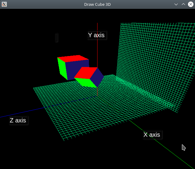
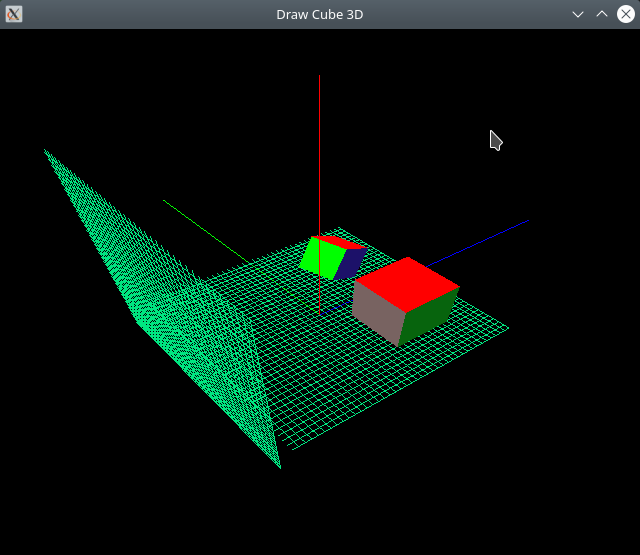
Project Files
Vertex Shader Code:
#version 330 core

layout ( location = 0)  in vec3 position;
layout ( location = 1) in vec3 color;
out vec3 out_color;
uniform mat4 u_model;       // Model matrix
uniform mat4 u_view;        // Camera's view matrix
uniform mat4 u_projection;  // Camera's projection matrix

void main()
{
    gl_Position = u_projection * u_view * u_model * vec4(position, 1.0);

    // Forward to fragment shader
    out_color = color; // vec3(0.56, 0.6, 0.0);
}
Fragment Shader Code:
#version 330

// This color comes from Vertex shader
in vec3 out_color;

void main()
{
    // Set vertex colors
    gl_FragColor =  vec4(out_color, 1.0);
    // gl_FragColor = vec4(0.3, 0.6, 0.0, 1.0);
}
File: CmakeLists.txt
cmake_minimum_required(VERSION 3.5)
project(GLFW_project)

set(CMAKE_CXX_STANDARD 17)
set(CMAKE_CXX_STANDARD_REQUIRED ON)
set(CMAKE_VERBOSE_MAKEFILE ON)

#================ GLFW Settings  ===============#

find_package(OpenGL REQUIRED)

include(FetchContent)

# Set GLFW Options before FectchContent_MakeAvailable
set( GLFW_BUILD_EXAMPLES OFF CACHE BOOL  "GLFW lib only" )
set( GLFW_BUILD_TESTS    OFF CACHE BOOL  "GLFW lib only" )
set( GLFW_BUILD_DOCS     OFF CACHE BOOL  "GLFW lib only" )
set( GLFW_BUILD_INSTALL  OFF CACHE BOOL  "GLFW lib only" )

# Donwload GLFW library
FetchContent_Declare(
  glfwlib
  URL   https://github.com/glfw/glfw/releases/download/3.3.2/glfw-3.3.2.zip
)
FetchContent_MakeAvailable(glfwlib)

# Download GLM (OpenGL math library for matrix and vectors transformation)
FetchContent_Declare(
  glm
  URL  https://github.com/g-truc/glm/archive/0.9.8.zip
)
FetchContent_MakeAvailable(glm)

# Download pre-compiled GLEW when building under Windows NT OS (x64)
IF(WIN32)
   FetchContent_Declare(
      glew-release
      URL  https://ufpr.dl.sourceforge.net/project/glew/glew/2.1.0/glew-2.1.0-win32.zip
   )
   FetchContent_MakeAvailable(glew-release)
   include_directories( ${glew-release_SOURCE_DIR}/include  ${glm_SOURCE_DIR} )
   link_directories(  ${glew-release_SOURCE_DIR}/lib/Release/x64 )

   set( GLEW_LIB_PATH1 ${glew-release_SOURCE_DIR}/lib/Release/x64/glew32.lib )
   set( GLEW_LIB_PATH2 ${glew-release_SOURCE_DIR}/lib/Release/x64/glew32s.lib )
ENDIF()


message( [DEBUG] " glm_SOURCE_DIR = ${glm_SOURCE_DIR} ")
include_directories(${glm_SOURCE_DIR})

MACRO(ADD_OPENGL_APP target sources)
   add_executable( ${target} ${sources} )
   message([TRACE] " Add OpenGL executable = ${target} ")

   target_link_libraries( ${target} glfw
                                    OpenGL::GL
                                    ${GLEW_LIB_PATH1}
                                    ${GLEW_LIB_PATH2} )

    IF(MINGW)
        # Statically link against MINGW dependencies
        # for making easier to deploy on other machines.
        target_link_options( ${target} PRIVATE
                                 -static-libgcc
                                 -static-libstdc++
                                 -Wl,-Bstatic,--whole-archive -lwinpthread
                                 -Wl,--no-whole-archive
                                 )
     ENDIF()


     # Copy GLEW DLL shared library to same directory as the executable.
     IF(WIN32)
        add_custom_command(TARGET ${target} POST_BUILD
                       COMMAND ${CMAKE_COMMAND} -E copy_if_different
                       "${glew-release_SOURCE_DIR}/bin/Release/x64/glew32.dll"
                       $<TARGET_FILE_DIR:${target}>)
     ENDIF()
ENDMACRO()


  # ======= TARGETS ===========================#

  ADD_OPENGL_APP( draw3d-cube draw3d-cube.cpp )
File: draw3d-cube.cpp
// Draw many colored triangles from a single VBO (Vertex Buffer Object)
#include <iostream>
#include <vector>
#include <array>
#include <cmath>
#include <functional>

// -------- OpenGL headers ---------//
//
#define GL_GLEXT_PROTOTYPES 1 // Necessary for OpenGL >= 3.0 functions
#define GL3_PROTOTYPES      1 // Necessary for OpenGL >= 3.0 functions

#if defined(_WIN32)
   #include <windows.h>
   #include <GL/glew.h>
#endif

#include <GL/gl.h>
#include <GLFW/glfw3.h>

// #include <GL/glew.h>
#include <GL/glu.h>

// --------- OpenGL Math Librar ------------//
#include <glm/glm.hpp>
#include <glm/gtc/matrix_transform.hpp>
#include <glm/gtc/type_ptr.hpp>
#include <glm/gtx/string_cast.hpp>

// #define GLUT_ENABLED

#if defined(GLUT_ENABLED)
    #include <GL/glut.h>
#endif

#define GL_CHECK(funcall)\
    do { \
        (funcall); \
        GLint error = glGetError();  \
        if(error == GL_NO_ERROR){ break; } \
        std::fprintf(stderr, " [OPENGL ERROR] Error code = %d ; line = %d ; call = '%s'  \n" \
                      , error, __LINE__, #funcall ); \
        abort(); \
    } while(0)

GLFWwindow* make_glfwWindowi(int  width, int height, const char* title);

// Compile some  shader
void compile_shader(GLuint m_program, const char* code, GLenum type);

// Send data from memory to GPU VBO memory
void send_buffer(   GLuint* pVao        // Pointer to VAO (Vertex Array Object) - allocated by caller
                  , GLuint* pVbo        // Pointer to VBO (Vertex Buffer Object) - allocated by caller
                  , GLsizei sizeBuffer  // Total buffer size in bytes
                  , void*   pBufffer    // Pointer to buffer
                  , GLint   shader_attr // Shader attribute location id
                  , GLint   size        // Number of coordinates of a given vertex
                  , GLenum  type        // Type of each element coordinate
                  );

// ------------ Basic Data Structures -----------//

// Wrapper for 2D vertex coordinates
struct Vertex3D{  GLfloat x, y, z;  };
// Wrapper for RGB colors
struct ColorRGB { GLfloat r, g, b; };

struct Geometry {
    std::vector<Vertex3D> vertices;
    std::vector<ColorRGB> colors;
};

struct RenderObject {
    GLuint     u_model;     // Shader uniform variable for model matrix
    GLuint     vao;         // Vertex Array object
    glm::mat4  model;       // Object model matrix
    GLenum     draw_type;   // Draw type
    GLint      n_vertices;  // Number of vertices

    RenderObject(){ model = glm::mat4(1.0);  }
    // Explicit copy constructor
    RenderObject(const RenderObject&) = default;
    // Explicit copy assignment operator
    RenderObject& operator=(const RenderObject&) = default;

    void render()
    {
        glUniformMatrix4fv(u_model, 1, GL_FALSE, glm::value_ptr(model) );
        glBindVertexArray(vao);
        glDrawArrays(draw_type, 0, n_vertices);
    }
};


Geometry make_grid_geometry(size_t n_grid, float dx, const ColorRGB& color);
Geometry make_cube_geometry(float w);

constexpr ColorRGB color_red   = {1.0, 0.0, 0.0};
constexpr ColorRGB color_green = {0.0, 1.0, 0.0};
constexpr ColorRGB color_blue  = {0.0, 0.0, 1.0};
constexpr ColorRGB color_yelllow    = { 0.80,  1.000, 0.100 };
constexpr ColorRGB color_gray       = { 0.47,  0.390, 0.380 };
constexpr ColorRGB color_dark_green = { 0.027, 0.392, 0.050 };
constexpr ColorRGB color_dark_blue  = { 0.109, 0.066, 0.411 };

// Send vertices to GPU
void send_vertices( GLuint* pVao, GLuint* pVbo,  GLint shader_attr
                ,   std::vector<Vertex3D>& vertices )
{
    send_buffer(pVao, pVbo, sizeof(Vertex3D) * vertices.size(), vertices.data(), shader_attr, 3, GL_FLOAT );
}

// Send color coordinates to GPU
void send_colors( GLuint* pVao, GLuint* pVbo,  GLint shader_attr
                ,   std::vector<ColorRGB>& vertices )
{
    send_buffer(pVao, pVbo, sizeof(Vertex3D) * vertices.size(), vertices.data(), shader_attr, 3, GL_FLOAT );
}

struct Camera{
    // Current location of camera in world coordinates
    glm::vec3 cam_eye  = { 2.0, 4.0, 5.0 };
    // Point to where the camera is looking at in world coordinates.
    glm::vec3 cam_targ = { 0.0, 0.0, 0.0  };
    // Current  camera up vector (orientation) - Y axis (default)
    glm::vec3 cam_up = { 0.0, 1.0, 0.0 };

    // Field of view
    float fov_angle = glm::radians(60.0);
    // Aspect ratio
    float aspect   = 1.0;
    float zFar     = 20.0;
    float zNear    = 0.1;

    // ID of shader's view uniform variable - for setting view matrix
    GLuint shader_uniform_view;
    // ID of shader's projection uniform variable for setting projection matrix.
    GLuint shader_uniform_proj;

    Camera(GLuint uniform_view, GLuint uniform_proj, float aspect):
        shader_uniform_view(uniform_view)
      , shader_uniform_proj(uniform_proj)
      , aspect(aspect)
    {  update_view();  }

    void update_view()
    {
        // Create View matrix that maps from world-space coordinates to
        // camera-space coordinates
        auto Tview = glm::lookAt(cam_eye, cam_targ, cam_up);

        // Create projection matrix coordinates that maps from
        // camera-space coordinates to NDC (Normalized Device Coordinates).
        auto Tproj = glm::perspective( fov_angle
                                     , aspect
                                     , zNear
                                     , zFar );
        // Set shader uniform variables.
        glUniformMatrix4fv(shader_uniform_view, 1, GL_FALSE, glm::value_ptr(Tview) );
        glUniformMatrix4fv(shader_uniform_proj, 1, GL_FALSE, glm::value_ptr(Tproj) );

    }

    // Rotate camera around Y axis
    void rotate_y(float angle)
    {
        float a = glm::radians(angle);
        float C = cosf(a), S = sinf(a);
        float x = this->cam_eye.x;
        float y = this->cam_eye.y;
        float z = this->cam_eye.z;
        // Apply Y-axis rotation matrix directly to Y axis.
        this->cam_eye.x = x * C + z * S;
        this->cam_eye.y = y;
        this->cam_eye.z = -x * S + z * C;
        this->update_view();
    }

};

int main(int argc, char** argv)
{

    /* Initialize the library */
    if (!glfwInit()){ return -1; }

    #if defined(GLUT_ENABLED)
        glutInit(&argc, argv);
    #endif

    // ====== S H A D E R - C O M P I L A T I O N ====//
    //                                                //

    GLFWwindow* window = make_glfwWindowi(640, 480, "Draw Cube 3D");

    // Note: The shader source code is at the end of file.
    extern const char* code_vertex_shader;
    extern const char* code_frag_shader;

    GLuint prog = glCreateProgram();
    // Compile shader code
    compile_shader(prog, code_vertex_shader, GL_VERTEX_SHADER  ) ;
    compile_shader(prog, code_frag_shader,   GL_FRAGMENT_SHADER );
    glUseProgram(prog);

    // Get shader uniform variable location for projection matrix
    // See shader code: "uniform mat4 projection;"
    const GLint u_proj  = glGetUniformLocation(prog, "u_projection");
    assert( u_proj >= 0 && "Failed to find u_projection uniform variable" );

    const GLint u_view = glGetUniformLocation(prog, "u_view");
    assert( u_proj >= 0 && "Failed to find u_view uniform variable" );

    // Get shader uniform variable  location for model matrix.
    const GLint u_model  = glGetUniformLocation(prog, "u_model");
    assert( u_model >= 0 && "Failed to find uniform variable" );

    // Get shader attribute location - the function glGetAttribLocation - returns (-1) on error.
    const GLint attr_position = glGetAttribLocation(prog, "position");
    assert( attr_position >= 0 && "Failed to get attribute location" );

    // Get shader attribute of color
    const GLint attr_color = glGetAttribLocation(prog, "color");
    if( attr_color < 0){ std::fprintf(stderr, " [WARNING] Shader color attribute location not found. \n"); };


    // ====== U P L O A D - TO - G P U =========================//
    //                                                          //

    // ----- Upload Cube vertices and colors ----------------//
        Geometry cube_geometry = make_cube_geometry(0.3);
    GLuint vao_cube     = 0;
    GLuint vbo_vertices = 0;
    GLuint vbo_colors   = 0;
    // Upload geometry cube data to GPU
    send_vertices(&vao_cube, &vbo_vertices, attr_position, cube_geometry.vertices);
    send_colors(&vao_cube, &vbo_colors, attr_color, cube_geometry.colors);
    std::fprintf(stderr, " [TRACE] vao_cube = %d \n", vao_cube );

    // ------- Upload grid vertices and colors ------------------//
    Geometry grid_geometry = make_grid_geometry(20, 0.1f, ColorRGB{0.0f, 0.9f, 0.5f});
    GLuint vao_grid = 0;
    GLuint vbo_grid_vertices = 0;
    send_vertices(&vao_grid, &vbo_grid_vertices, attr_position, grid_geometry.vertices);
    send_colors(&vao_grid, &vbo_grid_vertices, attr_color, grid_geometry.colors);

    // ----- X, Y, Z axis for visual debugging ----------------
    // X axis (GREEN) ; Y axis (RED); Z axis (BLUE)
    GLuint vao_axis = 0;
    GLuint vbo_axis_vertices = 0;
    GLuint vbo_axis_colors = 0;
    float axis_len = 5.0;

    // Each two points represents a unconnected line (GL_LINES)
    std::vector<Vertex3D> axis_vertices {
        // Line for X axis - from (0.0, 0.0, 0.0) to (axis_len, 0.0, 0.0)
          Vertex3D{0.0f, 0.0f, 0.0f}, Vertex3D{axis_len, 0.0f, 0.0f}
        // Line for Y axis
        , Vertex3D{0.0f, 0.0f, 0.0f}, Vertex3D{0.0f, axis_len, 0.0f}
        // Line for Z axis
        , Vertex3D{0.0f, 0.0f, 0.0f}, Vertex3D{0.0f, 0.0, axis_len}
    };

    auto axis_colors = std::vector<ColorRGB>{
          // Color of X axis line
          color_green, color_green
          // Color of Y axis line
         , color_red,  color_red
          // Color of Z axis line
         , color_blue, color_blue
    };

    send_vertices(&vao_axis, &vbo_axis_vertices, attr_position, axis_vertices);
    send_colors(&vao_axis,   &vbo_axis_colors,   attr_color,    axis_colors  );

    // ============== Set Shader Uniform Variables =============//
    //                                                          //

    int width, height;
    glfwGetWindowSize(window, &width, &height);
    // Window aspect ratio
    float aspect = static_cast<float>(width) / height;
    // Identity matrix
    const auto identity = glm::mat4(1.0);


    // Set projection matrix uniform variable
    glUniformMatrix4fv(u_proj, 1, GL_FALSE, glm::value_ptr(identity) );

    // ==== R E N D E R I N G - O B J E C T S ==========================//
    //                                                                  //

    RenderObject cube1{};
    cube1.vao        = vao_cube;
    cube1.u_model    = u_model;
    cube1.draw_type  = GL_QUADS;
    cube1.n_vertices = 24;
    // cube1.model = glm::scale(cube1.model, glm::vec3(0.5, 0.5, 0.5));
    cube1.model = glm::translate(cube1.model, glm::vec3(0.2, 1.20, +0.4));
    cube1.model = glm::rotate(cube1.model, glm::radians(45.0f), glm::vec3(1.0, 1.0, 0.0));

    // Call copy constructor (copy all data from cube1)
    RenderObject cube2 = cube1;
    cube2.model = glm::mat4(1.0);
    cube2.model = glm::translate(cube2.model, glm::vec3(-1.20, 1.2, 0.4));
    cube2.model = glm::scale(cube2.model, glm::vec3(1.5, 1.5, 1.5));
    // cube2.model = glm::rotate(cube2.model, glm::radians(60.0f), glm::vec3(1.0, 0.0, 1.0));


    // Grid in the plane containing the axis X and Y
    RenderObject grid_xy{};
    grid_xy.vao        = vao_grid;
    grid_xy.u_model    = u_model;
    grid_xy.draw_type  = GL_LINES; // Unconnected lines
    grid_xy.n_vertices = grid_geometry.vertices.size();
    grid_xy.model = glm::translate(grid_xy.model, glm::vec3(0.0, 1.5, -2.2));
    //grid_xy.model = glm::scale(grid_xy.model, glm::vec3(4.0, 4.0, 4.0));

    // Grid in the plane which contains the axis X and Z
    RenderObject grid_xz = grid_xy;
    grid_xz.model = glm::mat4(1.0);
    grid_xz.model = glm::rotate(grid_xz.model, glm::radians(-90.0f), glm::vec3(1.0, 0.0, 0.0));
     // grid_xz.model = glm::scale(grid_xz.model, glm::vec3(4.0, 4.0, 4.0));


    // Axis which is positioned at the origin of WCS (World Coordinate System)
    RenderObject axis_world;
    axis_world.u_model   = u_model;
    axis_world.vao       = vao_axis;
    axis_world.draw_type = GL_LINES;
    axis_world.n_vertices = axis_vertices.size();


    Camera camera(u_view, u_proj, width / height);

    //  ======= R E N D E R  - L O O P ============//
    //                                             //
    while ( !glfwWindowShouldClose(window) )
    {
        glClear(GL_COLOR_BUFFER_BIT  | GL_DEPTH_BUFFER_BIT);

        // ====== BEGIN RENDERING ============//

            // GL_CHECK( ::glutWireTeapot(0.50) );

            // ------ Draw Grid ----------
            axis_world.render();
            grid_xy.render();
            grid_xz.render();
            cube1.render();
            cube2.render();

        // ====== END RENDERING ==============//

        /* Swap front and back buffers */
        glfwSwapBuffers(window);
        /* Poll for and process events */
        glfwWaitEvents();

        if( glfwGetKey(window, 'Q' ) == GLFW_PRESS )
        {
             std::cout << " [TRACE] User typed Q =>> Shutdown program. Ok. " << '\n';
             break;
        }

        if( glfwGetKey(window, GLFW_KEY_RIGHT ) == GLFW_PRESS ){ camera.rotate_y(+10.0); }
        if( glfwGetKey(window, GLFW_KEY_LEFT  ) == GLFW_PRESS ){ camera.rotate_y(-10.0); }

        // Move camera up (positive Y axis)
        if( glfwGetKey(window, GLFW_KEY_UP  ) == GLFW_PRESS ){
            camera.cam_eye.y += 0.5;
            camera.update_view();
        }

        // Move camera down (negative Y axis)
        if( glfwGetKey(window, GLFW_KEY_DOWN  ) == GLFW_PRESS )
        {
            camera.cam_eye.y -= 0.5;
            camera.update_view();
        }

        // Rotate cube 1 in counter counter clockwise way around Y axis
        if( glfwGetKey(window, 'A'  ) == GLFW_PRESS )
        {
            cube1.model = glm::rotate( cube1.model, glm::radians(+10.0f), glm::vec3(0.0, 1.0, 0.0) );
        }
        // Rotate cube 1 in counter clockwise way around Y axis
        if( glfwGetKey(window, 'S'  ) == GLFW_PRESS )
        {
            cube1.model = glm::rotate( cube1.model, glm::radians(-10.0f), glm::vec3(0.0, 1.0, 0.0) );
        }

        // Rotate cube 1 in counter counter clockwise way around X axis (positive rotation)
        if( glfwGetKey(window, 'Z'  ) == GLFW_PRESS )
        {
            cube1.model = glm::rotate( cube1.model, glm::radians(+10.0f), glm::vec3(1.0, 0.0, 0.0) );
        }
        // Rotate cube 1 in counter counter clockwise way around X axis (negative rotation)
        if( glfwGetKey(window, 'X'  ) == GLFW_PRESS )
        {
            cube1.model = glm::rotate( cube1.model, glm::radians(-10.0f), glm::vec3(1.0, 0.0, 0.0) );
        }


    }

    glfwTerminate();
    return 0;

} // --- End of main() -----//


// ---------- S H A D E R - P R O G R A M S  -------------------------//
//

// Minimal vertex shader =>> Runs on the GPU and processes each vertex.
const char* code_vertex_shader = R"(
    #version 330 core

    layout ( location = 0)  in vec3 position;
    layout ( location = 1) in vec3 color;
    out vec3 out_color;
    uniform mat4 u_model;       // Model matrix
    uniform mat4 u_view;        // Camera's view matrix
    uniform mat4 u_projection;  // Camera's projection matrix

    void main()
    {
        gl_Position = u_projection * u_view * u_model * vec4(position, 1.0);

        // Forward to fragment shader
        out_color = color; // vec3(0.56, 0.6, 0.0);
    }

)";

// Fragment shader source code
const char* code_frag_shader = R"(
    #version 330

    // This color comes from Vertex shader
    in vec3 out_color;

    void main()
    {
        // Set vertex colors
        gl_FragColor =  vec4(out_color, 1.0);
        // gl_FragColor = vec4(0.3, 0.6, 0.0, 1.0);
    }
)";


    // ====== I M P L E M E N T A T I O N S ==========//

GLFWwindow*
make_glfwWindowi(int  width, int height, const char* title)
{

    glfwSetErrorCallback([](int error, const char* description)
                         { std::fprintf( stderr, " [GLFW ERROR] Error = %d ; Description = %s \n"
                                        , error, description);
                         });

    GLFWwindow* window = glfwCreateWindow(width, height, title, NULL, NULL);
    assert( window != nullptr && "Failed  to create Window");

    // OpenGL context
    glfwMakeContextCurrent(window);
    // Pain whole screen as black - dark screen colors are better
    // for avoding eye strain due long hours staring on monitor.
    glClearColor(0.0f, 0.0f, 0.0f, 1.0f);

    // Set - OpenGL Core Profile - version 3.3
    GL_CHECK( glfwWindowHint(GLFW_CONTEXT_VERSION_MAJOR, 3) );
    GL_CHECK( glfwWindowHint(GLFW_CONTEXT_VERSION_MINOR, 3) );
    GL_CHECK( glfwWindowHint(GLFW_OPENGL_PROFILE, GLFW_OPENGL_CORE_PROFILE) );

    GL_CHECK( glEnable(GL_COLOR_MATERIAL) );
    GL_CHECK( glEnable(GL_DEPTH_TEST)     );
    GL_CHECK( glEnable(GL_BLEND)          );

    return window;
}

void compile_shader(GLuint m_program, const char* code, GLenum type)
{
    GLint shader_id = glCreateShader( type );
    glShaderSource(shader_id, 1, &code, nullptr);
    glCompileShader(shader_id);

    GLint is_compiled = GL_FALSE;
    // Check shader compilation result
    glGetShaderiv(shader_id, GL_COMPILE_STATUS, &is_compiled);

    // If there is any shader compilation result,
    // print the error message.
    if( is_compiled == GL_FALSE)
    {
        GLint length;
        glGetShaderiv(shader_id, GL_INFO_LOG_LENGTH, &length);
        assert( length > 0 );

        std::string out(length + 1, 0x00);
        GLint chars_written;
        glGetShaderInfoLog(shader_id, length, &chars_written, out.data());
        std::cerr << " [SHADER ERROR] = " << out << '\n';
        // Abort the exection of current process.
        std::abort();
    }

    glAttachShader(m_program, shader_id);
    glDeleteShader(shader_id);
    glLinkProgram(m_program);
    GLint link_status = GL_FALSE;
    glGetProgramiv(m_program, GL_LINK_STATUS, &link_status);
    assert( link_status != GL_FALSE );
    // glUseProgram(m_program);
}

// Upload buffer from main memory to GPU VBO
// =>> Parameters VAO, VBO are allocated by the caller.
void send_buffer( GLuint* pVao, GLuint* pVbo, GLsizei sizeBuffer
                , void* pBufffer, GLint   shader_attr, GLint size
                , GLenum type)
{
    assert(pVao != nullptr);
    assert(pVbo != nullptr);
    GLuint& vao = *pVao;
    GLuint& vbo = *pVbo;
    // Generate and bind current VAO (Vertex Array Object)
    if(vao == 0){ glGenVertexArrays(1, &vao); }
    glBindVertexArray(vao);
    // Generate and bind current VBO (Vertex Buffer Object)
    glGenBuffers(1, &vbo);
    glBindBuffer(GL_ARRAY_BUFFER, vbo);
    // Upload data to current VBO buffer in GPU
    glBufferData(GL_ARRAY_BUFFER, sizeBuffer, pBufffer, GL_STATIC_DRAW);
    glEnableVertexAttribArray(shader_attr);
    // Set data layout - how data will be interpreted.
    glVertexAttribPointer(shader_attr, size, type, GL_FALSE, 0, nullptr);
    // ------ Disable Global state set by this function -----//
    // Unbind VAO
    glBindVertexArray(0);
    // Unbind VBO
    glBindBuffer(GL_ARRAY_BUFFER, vbo);
    // Disable current shader attribute
    glDisableVertexAttribArray(shader_attr);

}


Geometry
make_grid_geometry(size_t n_grid, float dx, const ColorRGB& color)
{
    std::vector<Vertex3D> grid_vertices;
    std::vector<ColorRGB> grid_colors ;

    float dy = dx;
    float grid_w  = n_grid * dx;
    float grid_h  = n_grid * dy;

    // Draw horizontal lines - parallel to X axis
    for(size_t n = 0; n < 2 * n_grid; n++)
    {
        // Line Vertex A (BEGIN)
        grid_vertices.push_back( Vertex3D{ -grid_w, dy * n - grid_h, 0 } );
        // Color of vertex A
        grid_colors.push_back(color);
        // Line Vertex B (END)
        grid_vertices.push_back( Vertex3D{ +grid_w, dy * n - grid_h, 0  } );
        // Color of vertex B
        grid_colors.push_back(color);
    }

     // Draw horizontal lines - parallel to Y axis
    for(size_t n = 0; n < 2 * n_grid; n++)
    {
        // Line point A (BEGIN)
        grid_vertices.push_back( Vertex3D{ dx * n - grid_w, -grid_h, 0 } );
        // Color of Vertex A
        grid_colors.push_back(color);
        // Line pojnt B (END)
        grid_vertices.push_back( Vertex3D{ dx * n - grid_w, +grid_h, 0  } );
        // Color of Vertex B
        grid_colors.push_back(color);

    }

    return Geometry{ grid_vertices, grid_colors };

}

Geometry
make_cube_geometry(float w)
{
    // Array of cube vertex coordinates (X, Y)
    auto vertices = std::vector<Vertex3D> {
        // Top face {y = w}
        { w, w, -w}
      , {-w, w, -w}
      , {-w, w,  w}
      , { w, w,  w}

      // Bottom face , {y = -w}
      , { w, -w,  w}
      , {-w, -w,  w}
      , {-w, -w, -w}
      , { w, -w, -w}

      // Front face  , {z = w}
      , { w,  w, w}
      , {-w,  w, w}
      , {-w, -w, w}
      , { w, -w, w}

      // Back face , {z = -w}
      , { w, -w, -w}
      , {-w, -w, -w}
      , {-w,  w, -w}
      , { w,  w, -w}

      // Left face , {x = -w}
      , {-w,  w,  w}
      , {-w,  w, -w}
      , {-w, -w, -w}
      , {-w, -w,  w}

      // Right face , {x = w}
      , {w,  w, -w}
      , {w,  w,  w}
      , {w, -w,  w}
      , {w, -w, -w}
    };

    // std::fprintf(stderr, " [TRACE] Number of cube vertices = %zu \n", cube_vertices.size() );

    auto colors = std::vector<ColorRGB> {
           color_red
        ,  color_red
        ,  color_red
        ,  color_red

        , color_blue
        , color_blue
        , color_blue
        , color_blue

        , color_green
        , color_green
        , color_green
        , color_green

        , color_gray
        , color_gray
        , color_gray
        , color_gray

        , color_dark_green
        , color_dark_green
        , color_dark_green
        , color_dark_green

        , color_dark_blue
        , color_dark_blue
        , color_dark_blue
        , color_dark_blue
    };

    return Geometry{ vertices, colors };
}
Building on Linux
$ cmake -H. -B_build_linux -DCMAKE_BUILD_TYPE=Debug
$ cmake --build _build_linux --target

$ ls _build_linux/
CMakeCache.txt  cmake_install.cmake  draw3d-cube*
CMakeFiles/     _deps/               Makefile
Run the application:
$ >> _build_linux/draw3d-cube
[TRACE] vao_cube = 1
Cross-compiling for Windows and testing with wine
STEP 1: Cmake configuration step
$ docker run -it --rm --user=$(id -u):$(id -g)  \
       --volume=$PWD:/cwd --workdir=/cwd  dockcross/windows-static-x64 \
       cmake -H. -B_build_cross -DCMAKE_BUILD_TYPE=Debug
STEP 2: Cmake building step
$ docker run -it --rm --user=(id -u):(id -g)  \
    --volume=$PWD:/cwd --workdir=/cwd  dockcross/windows-static-x64 \
    cmake --build _build_cross --target
STEP 3: Check compiled files
$ >> ls _build_cross/
CMakeCache.txt  cmake_install.cmake  draw3d-cube.exe*  Makefile
CMakeFiles/     _deps/               glew32.dll*
STEP 4: Run the application with Wine
 $ file _build_cross/draw3d-cube.exe
_build_cross/draw3d-cube.exe: PE32+ executable (console) x86-64, for MS Windows

 $ file _build_cross/glew32.dll
_build_cross/glew32.dll: PE32+ executable (DLL) (console) x86-64, for MS Windows

$ wine _build_cross/draw3d-cube.exe
1.23 3D - WebGL 3D Scene with grid and cube
By using WebGL API, it is possible to learn and prototype computer graphics without the complexity of dealing with building systems, compilation, memory management and C or C++ programming. This code takes advantage of the ubiquity and availability of JavaScript and WebGL on every modern web browser for demonstrating the usage of OpenGL and WebGL APIs for rendering a simple 3D scene containing a camera, grid, cube and tetrahedron. The sample WebGL application uses no external dependencies and implements everything from scratch which makes it easier to reason about the code and about 3D programming concepts.
Since the code is written in JavaScript and html, it is possible to experiment and play with webGL APIs used in the code by opening the next link.
- Live example available at: https://jsfiddle.net/kgqdocma/
In the live example, there are the following controls:
- 'a' key => rotates the camera view upwards (forward vector)
- 's' key => rotates the camera view downwards (forward)
- arrow up => Moves the camera position (eye vector) in the direction that camera is looking at (forward vector).
- arrow down => Moves the camera position (eye vector) in the opposite direction that the camera is looking at.
- arrow right => Rotates the camera around its up vector (orientation).
- arrow left => Rotates the camera in the opposite direction around its up vector (orientation).
- 'j' => Move the camera in the positive direction of Y axis
- 'k' => Move the camera in the negative direction of Y axis.
- 'q' => Rotates the cube.
- 'r' => Reset camera position (eye vector) and view (forward vector)
Notes:
- The class Matrix4x4 that represents a mutable 4x4 matrix column-major matrix is inspired by the c++ class QMatrix4x4 class from Qt framework.
- The Quaternion class was inspired by C++ class QQuaternion from Qt framework.
- The class Orientation was inspired by the C++ class FTransform from Unreal game engine. The idea was copied from public information available in the documentation.
- WebGL and OpenGL ES only support matrices in column-major order memory layout. Those APIs do not support matrices in row-major order.
- WebGL, which is based on OpenGL ES only supports the retained mode. WebGL does not support immediate mode. Therefore there is no equivalent in WebGL to the old and deprecated OpenGL retained mode APIs, including glVertex3f(), glBegin(), glEnd(), glColor(), glMaterial(), glRotate(), glTranslate(), glFrustum() and many other deprecated OpenGL subroutines.
- In modern OpenGL and specially in OpenGL ES and WebGL, it is only possible to draw primitive forms such as lines, points and triangles, any complex shape requires a good enough amount of primitive shapes in order to look like smooth and realistic.
Screenshots
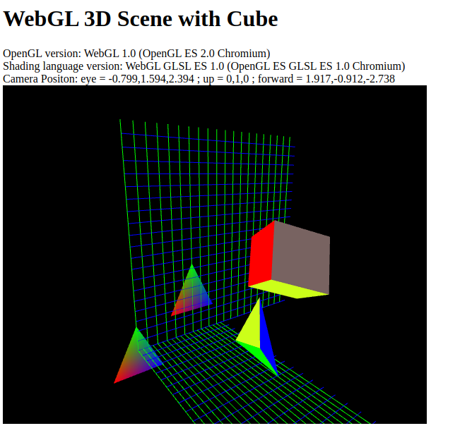
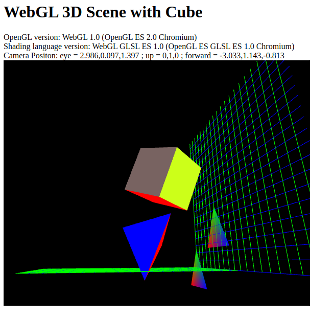
More about WebGL
- Drawing Area Polygons with WebGL
- https://learnwebgl.brown37.net/
- https://webglfundamentals.org/
- https://stackoverflow.com/questions/tagged/webgl
- WebGL: 2D and 3D graphics for the web - Mozilla
- https://webgl-shaders.com/
- https://web.dev/webgl-shaders/
- JavaScript Obfuscator Tool
Complete Html Code (File: webgl2.html)
<!DOCTYPE html>
<html>
   <head>
       <title>WebGL 3D Scene</title>
    </script>
   </head>

   <body>
       <h1>WebGL 3D Scene with Cube</h1>
       OpenGL version:  <label id="output1"></label>          <br/>
       Shading language version: <label id="output2"></label> <br/>
       Camera Position: <label id="output-camera"></label> <br/>
       <canvas id="glCanvas" width="600" height="480">
   </body>
    <script>
// eye = [3, 10, 20]; at = [50, 25, 10]; up = [0, 1, 0];

// RGB color constants (Red, Gree, Blue) (R, G, B) tuples
const COLOR_RED        = [1.0, 0.0, 0.0];
const COLOR_GREEN      = [0.0, 1.0, 0.0];
const COLOR_BLUE       = [0.0, 0.0, 1.0];
const COLOR_YELLLOW    = [ 0.80,  1.000, 0.100 ];
const COLOR_GRAY       = [ 0.47,  0.390, 0.380 ];
const COLOR_DARK_GREEN = [ 0.027, 0.392, 0.050 ];
const COLOR_DARK_BLUE  = [ 0.109, 0.066, 0.411 ];

  ... ... ..... . ... .... ... ... ... ...
  ... ... ..... . ... .... ... ... ... ...

    </script>

  </html>
JavaScript part:
// eye = [3, 10, 20]; at = [50, 25, 10]; up = [0, 1, 0];

// RGB color constants (Red, Gree, Blue) (R, G, B) tuples
const COLOR_RED        = [1.0, 0.0, 0.0];
const COLOR_GREEN      = [0.0, 1.0, 0.0];
const COLOR_BLUE       = [0.0, 0.0, 1.0];
const COLOR_YELLLOW    = [ 0.80,  1.000, 0.100 ];
const COLOR_GRAY       = [ 0.47,  0.390, 0.380 ];
const COLOR_DARK_GREEN = [ 0.027, 0.392, 0.050 ];
const COLOR_DARK_BLUE  = [ 0.109, 0.066, 0.411 ];


// Normalize a vector 3x1 column vector (3 rows and 1 column)
function normalize(vector)
{
  let [x, y, z] = vector;
  let norm = Math.sqrt( x * x + y * y + z * z);
  return [ x / norm, y / norm, z / norm ];
}

// Computes the dot product (aka scalar) product between two vectors
function dot(vectorA, vectorB)
{
  let [xa, ya, za] = vectorA;
  let [xb, yb, zb] = vectorB;
  return xa * xb  + ya * yb + za * zb;
}

// Computs the cross product between two vectors
function cross(vectorA, vectorB)
{
  let [xa, ya, za] = vectorA;
  let [xb, yb, zb] = vectorB;
  return [ ya * zb - za * yb, za * xb - xa * zb, xa * yb - ya * xb ];
}

// Difference between two vectors
function diff(vectorA, vectorB)
{
  let [xa, ya, za] = vectorA;
  let [xb, yb, zb] = vectorB;
  return [xa - xb, ya - yb, za - zb];
}

class Quaternion
{
  constructor(w, x, y, z)
  {
    // Default is the unit quaternion
    this._quat = [w, x, y, z];
  }

  /** @param {number} w
  /*  @param {number} x
  /*  @param {number} y
  /*  @param {number} z
   */
  static create(w, x, y, z)
  {
    return new Quaternion(w, x, y, z);
  }

  /** Create unit quaternion  */
  static createUnit()
  {
    return new Quaternion(1.0, 0.0, 0.0, 0.0);
  }

  /** Create a imaginary quaternion */
  static createFromVector(x, y, z)
  {
    return new Quaternion(0.0, x, y, z);
  }

  /** Create quaternion represeting a rotation around some axis
   * @param {number}   angle - Rotation angle in degrees
   * @param {number[]} axis  - Rotation axis
   */
  static createFromAxisAngle(angle, axis)
  {
    let [nx, ny, nz] = normalize(axis);
    // Angle in radians
    let t = angle / 180.0 * Math.PI / 2;
    let C = Math.cos(t);
    let S = Math.sin(t);
    return Quaternion.create(C, S * nx, S * ny, S * nz);
  }

  negate()
  {
    let [w, x, y, z] = this._quat;
    return new Quaternion(-w, -x, -y, -z);
  }

  conjugate()
  {
    let [w, x, y, z] = this._quat;
    return new Quaternion(w, -x, -y, -z);
  }

  // Note: It is assumed that the current quaternion is a unit quaternion
  rotateVector(v)
  {
    let qa = this;
    let qb = Quaternion.createFromVector(...v);
    // r1 = qa * qb
    let r1 = qa.multiply(qb);
    let r2 = r1.multiply(qa.conjugate());
    // r2 = qa * qb * qa.conjugage()
    //let b = q.multiply( qa.conjugate() );
    return r2.getVector();
  }

  /** Get imaginary part of a quaternion */
  getVector()
  {
    let [w, x, y, z] = this._quat;
    return [x, y, z];
  }

  /** Turn the quaternion into a homogeneous rotation matrix */
  toMatrix()
  {
    // The quaternion is assumed to be a unit quaternion
    // otherwise the matrix result will be invalid
    let [a, b, c, d] = this._quat;
    let m = new Float32Array(16);
    m[0] = a * a - c * c - d * d;
    m[1] = 2 * (b * c + a * d);
    m[2] = 2 * (b * d - a * c);
    m[3] = 0.0;

    m[4] = 2 * (b * c - a * d);
    m[5] = a * a - b * b + c * c -  d * d;
    m[6] = 2 * (c * d + a * b);
    m[7] = 0.0;

    m[8] = 2 * (b * d + a * c);
    m[9] = 2 * (c * d - a * b);
    m[10] = a * a - b * b - c * c + d * d;
    m[11] = 0;

    m[12] = 0.0;
    m[13] = 0.0;
    m[14] = 0.0;
    m[15] = 1.0;

    return m;
  }

  /** Multiply a quaternion for another and returns a new quaternion
   * Note: JavaScript lacks operator overloading
   * Note: Quaternion multiplication is not commutative
   * @param {Quaternio} q
   **/
  multiply( q )
  {
    let [w1, x1, y1, z1] = this._quat;
    let [w2, x2, y2, z2] = q._quat;
    let result = [
          w1 * w2 - x1 * x2 - y1 * y2 - z1 * z2
        , x1 * w2 + w1 * x2 - z1 * y2 + y1 * z2
        , y1 * w2 + z1 * x2 + w1 * y2 - x1 * z2
        , z1 * w2 - y1 * x2 + x1 * y2 + w1 * z2
    ];
    return new Quaternion(...result);
  }

}


class Matrix4x4
{

  constructor()
  {
      this.mat = new Float32Array(16);
      this.mat[0] = 1.0;
      this.mat[5] = 1.0;
      this.mat[10] = 1.0;
      this.mat[15] = 1.0;
  }

  static create()
  {
    return new Matrix4x4();
  }

  at(i, j)
  {
    return this.mat.at(j + 4 * i);
  }

  setToIdentity()
  {
      this.mat = new Float32Array(16);
      this.mat[0] = 1.0;
      this.mat[5] = 1.0;
      this.mat[10] = 1.0;
      this.mat[15] = 1.0;
      return this;
  }

  // this.matrix = this.matrix * translateMatrix(x, y, z)
  /**
   *  @param {number} x
   *  @param {number} y
   *  @param {number} z
   */
  translate(x, y, z)
  {
    let matrix = [   1, 0, 0, 0
                   , 0, 1, 0, 0
                   , 0, 0, 1, 0
                   , x, y, z, 1
                  ];
    this.multiply(matrix);
    return this;
  }

  translateV(vector)
  {
    this.translate(vector[0], vector[1], vector[2]);
    return this;
  }

  /**
   *  @param {number} sx
   *  @param {number} sy
   *  @param {number} sz
   */
  scaleV(sx, sy, sz)
  {
    let matrix = [  sx,  0,  0, 0
                   , 0, sy,  0, 0
                   , 0,  0, sz, 0
                   , 0,  0,  0, 1
                  ];
    this.multiply(matrix);
    return this;
  }

  /**
   *  @param {number} k
   */
  scale(k)
  {
     let m = new Float32Array(16);
     m[0] = k;
     m[5] = k;
     m[10] = k;
     m[15] = 1.0;
    this.multiply(m);
    return this;
  }

  // Rotation around arbitrary axis (vector) designated by X, Y, Z
  // the angle is in radians
  // this.matrix = this.matrix * rotate(angle, x, y, z)
  rotate(angle, x, y, z)
  {
    let r = new Float32Array(16);
    let t = angle * Math.PI / 180.0;
    let C = Math.cos(t);
    let S = Math.sin(t);
    let K = 1 - C ;
    r[0] = x*x + (1 - x*x)*C;
    r[4] = x*y*K - z*S;
    r[8] = x*z*K + y*S;
    r[12] = 0;
    r[1] = x*y*K + z*S;
    r[5] = y*y + (1 - y*y)*C
    r[9] = -x*S + y*z*K;
    r[13] = 0;
    r[2] = x*z*K - y*S;
    r[6] = x*S + y*z*K;
    r[10] = z*z + (1 - z*z)*C;
    r[14] = 0;
    r[3] = 0;
    r[7] = 0;
    r[11] = 0;
    r[15] = 1;
    this.multiply(r);
    return this;
  }

  /** Rotate around Z axis
   * @param {number} angle - Rotation angle in degrees
   */
  rotateZ(angle)
  {
    // let r = new Float32Array(16);
    let r = Array(16).fill(0.0);
    let t = angle * Math.PI / 180.0;
    let C = Math.cos(t);
    let S = Math.sin(t);
    r[0] = C; r[4] = -S;
    r[1] = S; r[5] =  C;
    r[10] = 1; r[15] = 1;

    this.multiply(r);
    //this.mat = r;
    return this;
  }

  /** Rotate around some axis
   * @param  {number}    angle  - rotation angle in degrees
   * @param  {number[]}  axis   - rotation axis as an array of 3 numbers
   */
  rotateAxis(angle, axis)
  {
    let [x, y, z] = axis;
    this.rotate(angle, x, y, z);
    return this;
  }

  /** Rotate current matrix by multiplying it by the quaternion rotation matrix
   *  this.matrix = this.matrix * quaternion.RotMatrix
   * @param {Quaternion} q
   **/
  rotateQuaternion(q)
  {
    let rotmatrix = q.toMatrix();
    this.multiply(rotmatrix);
    return this;
  }

  setLookAt(eye, at, up)
  {
    let Z = normalize( diff(eye, at) );
    let X = normalize( cross(up, Z) );
    let Y = normalize( cross(Z, X) );
    let m = new Float32Array(16);
    m[0]  = X[0]; m[4]  = X[1]; m[8]  = X[2];  m[12]  = -dot(X, eye);
    m[1]  = Y[0]; m[5]  = Y[1]; m[9]  = Y[2];  m[13]  = -dot(Y, eye);
    m[2]  = Z[0]; m[6]  = Z[1]; m[10] = Z[2];  m[14] = -dot(Z, eye);
    m[3] = 0;     m[7] = 0;     m[11] = 0;     m[15] =  1;
    this.mat = m;
    return this;
  }

  // FOV angle in degrees
  setPerspective(FOV, aspect, zNear, zFar)
  {
    // Angle in radians
    let t = Math.PI * FOV / 180.0;
    let k = Math.tan(t / 2);
    let m = new Float32Array(16);
    m[0] = 1 / ( aspect * k );
    m[5] = 1 / k;
    m[10] = (zNear + zFar) / (zNear - zFar);
    m[14] = 2 * zNear * zFar / (zNear - zFar);
    m[11] = -1;
    this.mat = m;
    return this;
  }

  // In place matrix multiplication
  multiply( matrix )
  {
    let a = this.mat;
    let b = matrix;
    let c = new Float32Array(16);

  // Matrix multiplication algorithm of column-major matrices borrowed from
  // https://github.com/yycho0108/Abstraction/blob/master/gl-matrix.min.js
   var d = a[0], e = a[1], g = a[2], f = a[3], h = a[4], i = a[5], j = a[6], k = a[7]
          , l = a[8], o = a[9], m = a[10], n = a[11], p = a[12], r = a[13], s = a[14];

    a = a[15];
    var A = b[0], B = b[1], t = b[2], u = b[3], v = b[4], w = b[5], x = b[6], y = b[7], z = b[8]
        , C = b[9], D = b[10], E = b[11], q = b[12], F = b[13], G = b[14];

    b = b[15];
    c[0] = A * d + B * h + t * l + u * p;
    c[1] = A * e + B * i + t * o + u * r;
    c[2] = A * g + B * j + t * m + u * s;
    c[3] = A * f + B * k + t * n + u * a;
    c[4] = v * d + w * h + x * l + y * p;
    c[5] = v * e + w * i + x * o + y * r;
    c[6] = v * g + w * j + x * m + y * s;
    c[7] = v * f + w * k + x * n + y * a;
    c[8] = z * d + C * h + D * l + E * p;
    c[9] = z * e + C * i + D * o + E * r;
    c[10] = z *
        g + C * j + D * m + E * s;
    c[11] = z * f + C * k + D * n + E * a;
    c[12] = q * d + F * h + G * l + b * p;
    c[13] = q * e + F * i + G * o + b * r;
    c[14] = q * g + F * j + G * m + b * s;
    c[15] = q * f + F * k + G * n + b * a;
    this.mat = c;
  }

}


function assertNotUndefined(variableName, variable)
{
  if( typeof variable == "undefined" )
  {
    alert(` [ASSERT ERROR] ${variableName} is undefined.`);
  }
}


    // Based on:  https://webglfundamentals.org/webgl/lessons/webgl-fundamentals.html
function compileShaderProgram(gl, vertexShaderCode, fragmentShaderCode)
{
    function createShader(gl, type, source)
    {
      assertNotUndefined("gl", gl);
      var shader = gl.createShader(type);
      gl.shaderSource(shader, source);
      gl.compileShader(shader);
      var success = gl.getShaderParameter(shader, gl.COMPILE_STATUS);
      if (success) {
        return shader;
      }

      console.log(" [SHADER ERROR] = \n" + source);
      console.log(" [SHADER ERROR] "  + gl.getShaderInfoLog(shader) );
      // alert(" [SHADER ERORR]  " + gl.getShaderInfoLog(shader) );
      gl.deleteShader(shader);
    }

    let vertexShader = createShader(gl, gl.VERTEX_SHADER, vertexShaderCode);

    let fragmentShader = createShader(gl, gl.FRAGMENT_SHADER, fragmentShaderCode);
    console.log(" [TRACE] Compiled fragmentShader Ok.");

    var program = gl.createProgram();
    assertNotUndefined("program", program);
    gl.attachShader(program, vertexShader);
    console.log(" [TRACE] Attach vertex shader Ok");
    gl.attachShader(program, fragmentShader);
    console.log(" [TRACE] Attach fragment shader Ok");
    gl.linkProgram(program);
    var success = gl.getProgramParameter(program, gl.LINK_STATUS);
    if (success) {
      return program;
    }

    console.error(gl.getProgramInfoLog(program));
    gl.deleteProgram(program);
}


function resizeCanvasToDisplaySize(canvas, multiplier)
{
    multiplier = multiplier || 1;
    const width  = canvas.clientWidth  * multiplier | 0;
    const height = canvas.clientHeight * multiplier | 0;
    if (canvas.width !== width ||  canvas.height !== height) {
      canvas.width  = width;
      canvas.height = height;
      return true;
    }
    return false;
}

// Vertex Buffer Object abstraction
class Vbuffer
{
  constructor(gl, attr_position, attr_color)
  {
    this._gl = gl;
    this._vbo = gl.createBuffer();
    this._data = new Float32Array(1);
    this._attr_position = attr_position;
    this._attr_color = attr_color;
    this._vertices = 0;
  }

  unbind()
  {
    let gl = this._gl;
    gl.bindBuffer(gl.ARRAY_BUFFER, null);
  }

  // Release the VBO from the GPU
  free()
  {
    let gl = this._gl;
    gl.deleteBuffer(this._vbo);
  }

  setData(data, ncomps = 3, stride = 0, istride = 0 )
  {
    let gl = this._gl;
    this._ncomps = ncomps;
    this._stride = stride;
    this._istide = 0;
    this._vertices = data.length;
    gl.bindBuffer( gl.ARRAY_BUFFER, this._vbo );
    this._data = new Float32Array(data);
    // Send data to GPU
    gl.bufferData(gl.ARRAY_BUFFER, this._data, gl.STATIC_DRAW);
  }

  drawTriangles()
  {
    let gl = this._gl;
    this.draw(gl.TRIANGLES);
  }

  drawLines()
  {
    let gl = this._gl;
    this.draw(gl.LINES);
  }

  drawLineLoop()
  {

    let gl = this._gl;
    this.draw(gl.LINE_LOOP);
  }

  draw(drawType)
  {
    let gl = this._gl;
    gl.bindBuffer( gl.ARRAY_BUFFER, this._vbo );

    // Position data layout for each vertex
    gl.vertexAttribPointer(  this._attr_position  // Shader attribute
                           , 3                    // Number of components, coordinates
                           , gl.FLOAT             // Type of each componente
                           , false                // Normalized flag
                           , 24                   // Stride  = sizeof(Vertex) = sizeof(Position) + sizeof(Color) =
                                                  // Stride  = 3 * sizeof(Float in bytes) + 3 * sizeof(Float in bytes)
                                                  // Stride  = 3 * 4 + 3 * 4 = 24
                           , 0                    // offset
                          );

    // Color data layout for each vertex
    gl.vertexAttribPointer(  this._attr_color     // Shader attribute
                           , 3                    // Number of components, coordinates
                           , gl.FLOAT             // Type of each componente
                           , false                // Normalized flag
                           , 24                   // Stride
                           , 12                   // offset - offset of color attribute = 3 * sizeof(float) =  3 * 4 = 12
                          );


    // Each vertex has 6 coordinates - 3 coordinates for position and 3 coordinates for color
    gl.drawArrays(drawType, 0, this._vertices / 6);

    // Unbind VBO and disable global state
    gl.bindBuffer( gl.ARRAY_BUFFER, null);
  }
}

class Camera
{
  constructor(gl, uniform_view, uniform_proj, uniform_eye)
  {
    // Current location of camera in world coordinates
    this.eye     = [  2.0, 4.0,  5.0 ];
    // Direction to where camera is looking at.
    this.forward = [ -1.0, 0.0, -1.0 ];
    // UP vector - camera orientation (default Y axis)
    this.up      = [  0.0, 1.0,  0.0 ];

    // Field of view angle stated in degrees
    this.fov_angle = 60.0;
    // Aspect ratio
    this.aspect = gl.canvas.clientWidth / gl.canvas.clientHeight;
    // Far
    this.zFar = 100.0;
    // Near
    this.zNear = 0.1;

    this.gl = gl;
    this.uniform_view = uniform_view;
    this.uniform_proj = uniform_proj;
    this.uniform_eye  = uniform_eye;

    this.updateView();

    console.log(" [TRACE] Crated Camera Ok.");
  }

  // Reset camera to initial position
  reset()
  {
    // Current location of camera in world coordinates
    this.eye     = [  2.0, 4.0,  5.0 ];
    // Direction to where camera is looking at.
    this.forward = [ -1.0, 0.0, -1.0 ];
    // Direction to where camera is looking at.
    this.up      = [  0.0, 1.0,  0.0 ];
    // Field of view angle stated in radians. It is by default 60 degrees.
    this.fov_angle = 60.0; //* Math.PI / 180.0;
  }

  // Rotate around camera's Up vecto.
  rotateYaw(angle)
  {
    let q = Quaternion.createFromAxisAngle(angle, this.up);
    this.forward = q.rotateVector(this.forward);
    this.updateView();
  }

  // Rotate around camera's pitch axis (X axis) elevate camera view.
  rotatePitch(angle)
  {
    let axis = cross(this.up, this.forward);
    let q = Quaternion.createFromAxisAngle(angle, axis);
    this.forward = q.rotateVector(this.forward);
    this.updateView();
  }

  // Move camera in Y axis
  moveCameraUpDow(factor)
  {
    // Increase of decrease Y component of Eye vector
    this.eye[1] = this.eye[1] + factor;
    this.updateView();
    return this;
  }

  // Make the vector forward parallel to the plane XZ
  parallelXZ()
  {
    this.forward[1] = 0.0;
    this.updateView();
    return this;
  }

     // Move at forward vector direction (to where camera is looking at).
  moveForward(factor)
  {
      // this->eye = this->eye + factor * this->forward;
      let [ex, ey, ez] = this.eye;
      let [fx, fy, fz] = this.forward;
      this.eye = [ex + factor * fx, ey + factor * fz, ez + factor * fz];
      this.updateView();
      return this
  }

  // Set camera position in world coordinates
  setPosition(position)
  {
    this.eye = position;
    this.updateView();
    return this;
  }

  setPositonXYZ(x, y, z)
  {
    this.setPosition([x, y, z]);
    return this;
  }

  lookAt(at)
  {
    // Set position to where camera is looking at.
    this.forward = diff(at, this.eye) ;
    this.updateView();
    return this;
  }

  lookAtXYZ(x, y, z)
  {
    this.lookAt([x, y, z]);
    return this;
  }


  updateView()
  {
    // Perspective/Projection matrix
    // Tp = glm::perspective( fov_angle, aspect, zNear, zFar );
    const Tp = new Matrix4x4();
    Tp.setPerspective(this.fov_angle, this.aspect, this.zNear, this.zFar);
    // console.log(" [TRACE] Tp = ", Tp);

    // View matrix
    // auto Tview = glm::lookAt(eye, cam_at, up);
    const Tv = new Matrix4x4();
    // Location where camera is looking at in world coordinates
    const at = [ this.eye[0] + this.forward[0], this.eye[1] + this.forward[1], this.eye[2] + this.forward[2] ];
    Tv.setLookAt(this.eye, at, this.up);
    // console.log(" [TRACE] Tv = ", Tv);

    // glUniformMatrix4fv(shader_uniform_view, 1, GL_FALSE, glm::value_ptr(Tview) );
    this.gl.uniformMatrix4fv(this.uniform_view, false, Tv.mat);

    // glUniformMatrix4fv(shader_uniform_proj, 1, GL_FALSE, glm::value_ptr(Tproj) );
    this.gl.uniformMatrix4fv(this.uniform_proj, false, Tp.mat);

  }

  setIdentity()
  {
    let m = new Matrix4x4();
    this.gl.uniformMatrix4fv(this.uniform_view, false, m.mat);
    this.gl.uniformMatrix4fv(this.uniform_proj, false, m.mat);
  }

}


/** Encapsulates the position, scale and  rotation of an object in the space */
class Orientation
{
  constructor()
  {
    // Default scale 1.0 - original object size
    this._scale     = 1.0;
    // Default position at origin
    this._position  = [0.0, 0.0, 0.0];
    // Unit quaternion
    this._rotation = Quaternion.create(1.0, 0.0, 0.0, 0.0);
    this._is_changed = false;
    this._model = Matrix4x4.create()
                          .translateV(this._position)
                          .scale(this._scale)
                          .rotateQuaternion(this._rotation)
  }

  reset()
  {
    this._scale     = 1.0;
    this._position  = [0.0, 0.0, 0.0];
    this.__rotation = Quaternion.create(1.0, 0.0, 0.0);
    this._is_changed = true;
  }

  setPosition(x, y, z)
  {
    this._position = [x, y, z];
    this._is_changed = true;
  }

  translate(dx, dy, dz)
  {
      this._position[0] += dx;
      this._position[1] += dy;
      this._position[2] += dz;
      this._is_changed = true;
      return this;
  }

  setScale(scale)
  {
      this.scale = scale;
      this.is_changed = true;
      return this;
  }

  rotateZ(angle)
  {
    // console.log(" [TRACE] Rotating angle = ", angle);
    // this.angle = this.angle + angle;
    this.rotate(angle, [0.0, 0.0, 1.0]);
    this._is_changed = true;
    return this;
  }

  rotate(angle, axis)
  {
    let q = Quaternion.createFromAxisAngle(angle, axis);
    this._rotation = this._rotation.multiply(q);
    this._is_changed = true;
    return this;
  }

  getModel()
  {
    if( this._is_changed )
    {
        this._is_changed = false;
        this._model.setToIdentity()
                  .translateV(this._position)
                  .scale(this._scale)
                  .rotateQuaternion(this._rotation);
    }
    return this._model;
  }

}

class Entity
{
  constructor(gl, vbo, u_model, drawType)
  {
    this.gl = gl;
    this.vbo = vbo;
    this.u_model = u_model;

    this.is_visible = true;

    // Draw Triangles by default
    this.drawType = drawType;
    this.orientaton = new Orientation();
  }

  setDrawTriangles() { this.drawType = this.gl.TRIANGLES; return this; }
  setDrawLines() { this.drawType = this.gl.LINES;         return this; }
  setDrawLineLoop() { this.drawType = this.gl.LINE_LOOP;  return this; }
  setVisible(flag) { this.is_visible = flag;              return this; }
  toggleVisible() { this.is_visible = !this.is_visible;         return this; }
  setPosition(x, y, z) { this.orientaton.setPosition(x, y, z);  return this; }
  translate(dx, dy, dz){ this.orientaton.translate(dx, dy, dz); return this; }
  setScale(k){ this.orientaton.setScale(k);                     return this; }
  rotateZ(angle){ this.orientaton.rotateZ(angle);               return this; }
  rotate(angle, axis){ this.orientaton.rotate(angle, axis);     return this; }

  draw()
  {
    let model = this.orientaton.getModel();
    if( this.is_visible )
    {
       this.gl.uniformMatrix4fv(u_model, false, model.mat);
       this.vbo.draw(this.drawType);
    }
  }
}

class EntityFactory
{

  /** @param {Vbuffer} - vbo */
  constructor(gl, vbo, u_model)
  {
    this.gl = gl;
    this.vbo = vbo;
    this.u_model = u_model;
    this.drawType = gl.TRIANGLES;
  }

  setDrawTriangles()
  {
    this.drawType = this.gl.TRIANGLES;
    return this;
  }

  setDrawLines()
  {
    this.drawType = this.gl.LINES;
    return this;
  }

  setDrawLineLoop()
  {
    this.drawType = this.gl.LINE_LOOP;
    return this;
  }

  create()
  {
      return new Entity(this.gl, this.vbo, this.u_model, this.drawType);
  }
}

    // ----- R E N D E R I N  G ------------------//


// Vertex Shader code => Performs vertex coordinate transforms in the GPU
let code_shader_vert =`
  // precision mediump float;

  // Note: keyword attribute is deprecated
  attribute vec3 position;
  attribute vec3 color;

  varying vec3 out_color;

  uniform vec3 u_eye;         // Cameras's position in space
  uniform mat4 u_model;       // Model matrix
  uniform mat4 u_view;        // Camera's view matrix
  uniform mat4 u_projection;  // Camera's projection matrix

  void main(){

    gl_Position = u_projection * u_view * u_model * vec4(position, 1.0);

    // Forward to fragment shader
    out_color = color;

  }
`;

// Fragment shader code => Sets color, lights and illumination
let code_shader_frag = `
   // precision mediump float;

   // varying low vec3 out_color;
   varying lowp vec3 out_color;

    void main()
    {
      gl_FragColor = vec4(out_color, 1.0);
      //gl_FragColor = vec4(0, 0, 1.0, 1.0);
    }
`;

  // ----------- Rendering Starts Here -----------//


const canvas = document.querySelector("#glCanvas");
const gl = canvas.getContext("webgl");

if(  gl == null ){
  alert(" [ABORT] Unable to initialized WebGL");
}

console.log(" [DEBUG] OpenGL version = " + gl.getParameter(gl.VERSION) );
console.log(" [DEBUG] Shading language version = " + gl.getParameter(gl.SHADING_LANGUAGE_VERSION));

document.querySelector("#output1").textContent = gl.getParameter(gl.VERSION);
document.querySelector("#output2").textContent =  gl.getParameter(gl.SHADING_LANGUAGE_VERSION);

let prog =  compileShaderProgram(gl, code_shader_vert, code_shader_frag);
gl.useProgram(prog);

// Uniform variables
let u_proj       = gl.getUniformLocation( prog, "u_projection");
let u_view       = gl.getUniformLocation( prog, "u_view");
let u_model      = gl.getUniformLocation( prog, "u_model");
let u_camera_eye = gl.getUniformLocation( prog, "u_eye");

// Attribute Locations
let attr_position = gl.getAttribLocation(prog, "position");
let attr_color    = gl.getAttribLocation(prog, "color");

let identity = new Matrix4x4();

// Initialize with identity matrix
gl.uniformMatrix4fv(u_model, false, identity.mat);
gl.uniformMatrix4fv(u_view,  false, identity.mat);
gl.uniformMatrix4fv(u_proj,  false, identity.mat);


function buildGridPlaneXY(gl, attr_position, attr_color, n , delta)
{
    let vertices = [];

    let xmax = n * delta;
    let ymax = n * delta;

    // Draw lines in plane XY parallel to line X
    for(let i = 0; i < n; i++)
    {
      // Position of first vertex
      let position1 = [0.0, i * delta, 0.0 ];
      // Positon of first line vertex
      vertices.push(...position1);
      // Color of second line vertex
      vertices.push(...COLOR_BLUE);

      // Position of second vertex
      let position2 = [xmax, i * delta, 0.0];
      // Positon of first line vertex
      vertices.push(...position2);
      // Color of second line vertex
      vertices.push(...COLOR_BLUE);
    }

    // Draw lines in plane XY parallel to line Y
    for(let j = 0; j < n; j++)
    {
      // Position of first vertex
      let position1 = [j * delta, 0.0, 0.0 ];
      // Positon of first line vertex
      vertices.push(...position1);
      // Color of second line vertex
      vertices.push(...COLOR_GREEN);

      // Position of second vertex
      let position2 = [j * delta, ymax, 0.0];
      // Positon of first line vertex
      vertices.push(...position2);
      // Color of second line vertex
      vertices.push(...COLOR_GREEN);
    }

    let buffer = new Vbuffer(gl, attr_position, attr_color);
    buffer.setData(vertices);
    return buffer;
}

function buildTetrahedron(gl, attr_position, attr_color, size)
{
  let k = size;
  // Position of Tetrahedron vertices
  let a = [0, 0, k];  // Point in Z axis
  let b = [k, 0, 0];  // Point in X axis
  let c = [0, k, 0];  // Point in Y axis
  let d = [0, 0, 0];  // Point in origin

  let COLOR_Triangle1 = COLOR_BLUE;
  let COLOR_Triangle2 = COLOR_GREEN;
  let COLOR_Triangle3 = COLOR_RED;
  let COLOR_Triangle4 = COLOR_YELLLOW;

  let vertices = [];

  // triangle vertices of face 1
  vertices.push(...a, ...COLOR_Triangle1);
  vertices.push(...b, ...COLOR_Triangle1);
  vertices.push(...c, ...COLOR_Triangle1);

  // triangle vertices of face 2
  vertices.push(...a, ...COLOR_Triangle2);
  vertices.push(...c, ...COLOR_Triangle2);
  vertices.push(...d, ...COLOR_Triangle2);

  // triangle vertices of face 3
  vertices.push(...a, ...COLOR_Triangle3);
  vertices.push(...b, ...COLOR_Triangle3);
  vertices.push(...d, ...COLOR_Triangle3);

  // triangle vertices of face 4
  vertices.push(...d, ...COLOR_Triangle4);
  vertices.push(...c, ...COLOR_Triangle4);
  vertices.push(...b, ...COLOR_Triangle4);

  // console.log(" [TRACE] vertices = ", vertices);

  let buffer = new Vbuffer(gl, attr_position, attr_color);
  buffer.setData(vertices);
  return buffer;
}

// Note: OpenGL can only draw triangles and lines.
// Therefore, the only way to draw a cube solid is to
// draw the triangles for every face of the  cube.
// As a cube has 6 face and two triangles for every
// face, it is necessary to draw 12 triangles.
function buildCube(gl, attr_position, attr_color, size)
{
  let k = size;
  // Cube vertices
  //       x  y  z
  let a = [0, 0, k];
  let b = [0, k, k];
  let c = [k, k, k];
  let d = [k, 0, k];
  let e = [k, 0, 0];
  let f = [k, k, 0];
  let g = [0, k, 0];
  let h = [0, 0, 0];

  let vertices = [];

  function triangle(t1, t2, t3, color)
  {
    vertices.push(...t1, ...color);
    vertices.push(...t2, ...color);
    vertices.push(...t3, ...color);
  }
  // Face 1 of cube
  triangle(a, b, c, COLOR_BLUE);
  triangle(a, c, d, COLOR_BLUE);
  // Face 2 of cube
  triangle(c, d, e, COLOR_DARK_GREEN);
  triangle(c, f, e, COLOR_DARK_BLUE);
  // Face 3 of cube
  triangle(a, d, e, COLOR_GREEN);
  triangle(a, h, e, COLOR_GREEN);
  // Face  4 of cube
  triangle(a, h, g, COLOR_YELLLOW);
  triangle(a, b, g, COLOR_YELLLOW);
  // Face  5 of cube
  triangle(b, c, g, COLOR_GRAY);
  triangle(c, g, f, COLOR_GRAY);
  // Face 6 of cube
  triangle(g, h, f, COLOR_RED);
  triangle(h, f, e, COLOR_RED);

  console.log(" [TRACE] vertices = ", vertices);

  let buffer = new Vbuffer(gl, attr_position, attr_color);
  buffer.setData(vertices);
  return buffer;
}


// Vertices of (x, y) coordinates
let vertices_triangle = [
   // --- Vertices ----- //  // (R, G, B) --- Colors -----//
    -0.25,  -0.25,  0,      1.0, 0.0, 0.0
  ,  0.00,  +0.25,  0,      0.0, 1.0, 0.0
  , +0.25,  -0.25,  0,      0.0, 0.0, 1.0
];

// Upload vertices GPU

let vboGrid = buildGridPlaneXY(gl, attr_position, attr_color, 20, 0.1);
let gridFactory = new EntityFactory(gl, vboGrid, u_model).setDrawLines();
let gridXY = gridFactory.create();
let gridXZ = gridFactory.create().rotate(90.0, [1.0, 0.0, 0.0]);


let vboTetrahedron = buildTetrahedron(gl, attr_position, attr_color, 0.50);
let TetrahedronFactory = new EntityFactory(gl, vboTetrahedron, u_model);
let tetrahedron1 = TetrahedronFactory.create();
tetrahedron1.translate(0.6, 0.25, 0.70).rotate(70, [5, 2, 3]);

let tetrahedron2 = TetrahedronFactory.create();
tetrahedron2.setDrawLineLoop();
tetrahedron2.translate(1.0, 1.25, 0.9).rotate(70, [1, 2, 2]);

let vboCube = buildCube(gl, attr_position, attr_color, 0.50);
let cubeFactory = new EntityFactory(gl, vboCube, u_model);
let cube1 = cubeFactory.create().translate(0.9, 0.60, 0.50).rotate(80, [1, 1, 1]);


let vboTriangle = new Vbuffer(gl, attr_position, attr_color);
vboTriangle.setData(vertices_triangle);
const triangleFactory = new EntityFactory(gl, vboTriangle, u_model);

let triangle1 = triangleFactory.create();
triangle1.draw();

let triangle2 = triangleFactory.create();
triangle2.setPosition(0.60, 0.50, 0.0);
triangle2.setScale(1.25);
triangle2.draw();


gl.enableVertexAttribArray(attr_position);
gl.enableVertexAttribArray(attr_color);


let camera = new Camera(gl, u_view, u_proj, u_camera_eye)
camera.setPosition( [2, 2, 2 ]).lookAt( [0, 0, 0] );


function drawScene()
{
    // resizeCanvasToDisplaySize(gl.canvas);
    gl.viewport(0, 0, gl.canvas.width, gl.canvas.height);
    // Screen background color is black
    // => clearColor(Red intensity from 0 to 1, Green , Blue , Alpha)
    gl.clearColor(0.0, 0.0, 0.0, 1.0);
    gl.clear(gl.COLOR_BUFFER_BIT);
    gl.clearDepth(1.0);         // Clear everything
    gl.enable(gl.DEPTH_TEST);   // Enable depth testing
    gl.depthFunc(gl.LEQUAL);    // Near things obscure far things
    gl.clear(gl.COLOR_BUFFER_BIT | gl.DEPTH_BUFFER_BIT);

    triangle1.draw();
    triangle2.draw();
    // triangleA.draw();
    // triangleB.draw();

    gridXY.draw();
    gridXZ.draw();

    tetrahedron1.draw();
    // tetrahedron2.draw();
    cube1.draw();

}

drawScene();

const KEY_ARROW_LEFT  = 37;
const KEY_ARROW_RIGHT = 39;
const KEY_ARROW_DOWN  = 40;
const KEY_ARROW_UP    = 38;

function precisionRound(vector, digits)
{
  let factor = Math.pow(10, digits);
  return vector.map(x => Math.round(x * factor) / factor);
}

function keyboardListener(event)
{
    /** @param {number} key */
    let key = event.keyCode;

    // console.log(" [TRACE] type(event) = ", typeof(event));
    // console.log(" [TRACE] Event = ", event);

    if( key == KEY_ARROW_LEFT )
    {
      // triangle1.translate(-0.10, 0.0, 0.0);
      camera.rotateYaw(10.0);
    }

    if( key == KEY_ARROW_RIGHT  )
    {
      // triangle1.translate(+0.10, 0.0, 0.0);
      camera.rotateYaw(-10.0);
    }

    if( key == KEY_ARROW_UP  )
    {
      // triangle1.translate(0.0, 0.1, 0.0);
      camera.moveForward(0.2);
    }

    if( key == KEY_ARROW_DOWN  )
    {
      // triangle1.translate(0.0, -0.1, 0.0);
      camera.moveForward(-0.2);
    }

    // Elevate camera view, rotate the forward vector upwards
    if( event.key == "a" )
    {
      camera.rotatePitch(10.0);
    }

    // Rotate camera view downwards
    if( event.key == "s")
    {
      camera.rotatePitch(-10.0);
    }

    if( event.key == "q")
    {
      cube1.rotate(25, [1, 2, 1]);
    }

    if( event.key == "w")
    {
      console.log(" Rotate -10 degrees ");
      triangle1.rotateZ(-10.0);
    }

    if( event.key == "o")
    {
      // triangle1.setVisible(true);
      cube1.setDrawTriangles();
    }

    if(  event.key == "p" )
    {
      // triangle1.setVisible(false);
      cube1.setDrawLineLoop();
    }

    // Move camera in the positive direction of Y axis
    if( event.key === "j" ){ camera.moveCameraUpDow(+0.1); }
    // Move camera in the negative direction of Y axis
    if( event.key === "k" ){ camera.moveCameraUpDow(-0.1); }

    // Make the vector forward parallel to the plane XZ
    if( event.key == "h"){ camera.parallelXZ(); }

    let eye =  precisionRound(camera.eye, 3);
    let up =   precisionRound(camera.up, 3);
    let forward = precisionRound(camera.forward, 3);
    document.querySelector("#output-camera").textContent = `eye = ${eye} ; up = ${up} ; forward = ${forward}`;

    drawScene();
}

addEventListener("keydown", keyboardListener);
1.24 3D - Quaternion
The class Transform has the fields, position for setting the object position in world-coordinates; scale for adjusting object size and rotation, which is a quaternion for encoding rotation around an arbitrary axis. The use of quaternions saves the usage of many matrix multiplications for each transform and also allows easier accumulation of intermediate rotations.
Quaternions are also used in the camera class for providing YRP (Yaw-Pitch-Roll) camera rotation and free movement in the space. The keys arrow-left, arrow-right rotates the direction to where camera is looking at to right or to the left. The key arrow-up, moves the camera position in the direction to where the camera is looking at. The key arrow-down moves the camera in the backward direction to where the camera is looking at. The key 'S' rotates the camera up, the key 'D' rotates the camera down.
The scene, has a blue square on the plane XY; a green square on plane XZ; a teapot and torus. The torus can be moved, scaled and rotated in the space by just changing its transform object parameters. By typing the key 'B', the teapot scale is increased, and by typing 'N' its scale is decrease. The keys 'J', 'L' rotates the teapot around the Y axis. The key 'P' moves the teapot up across Y axis. The key 'O' moves the teapot down across the Y axis.
Note: This code requires the GLUT library which provides the sample wireframe teapot and torus.
Screenshots
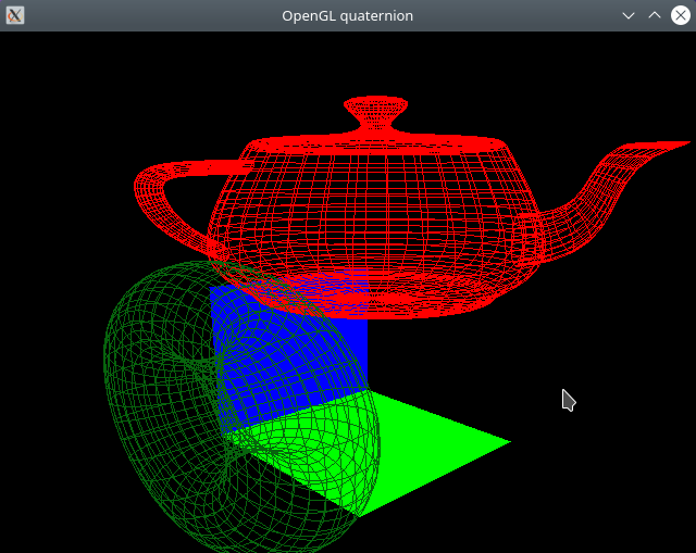
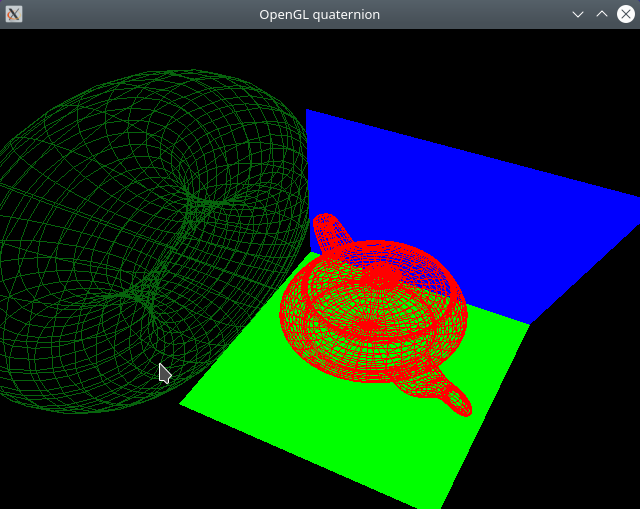
Code Highlights
Transform class using quaternion:
// Transform object that combines - translation, scale and rotation (quaternion)
struct Transform
{
    glm::vec4 position = {0.0, 0.0, 0.0, 1.0};
    glm::vec3 scale    = {1.0, 1.0, 1.0};
    glm::quat rotation = {1.0, 0.0, 0.0, 0.0};

    void set_scale(float k){ scale[0]  = k; scale[1] = k;  scale[2]  = k;  }
    void add_scale(float k){ scale[0] += k; scale[1] += k; scale[2] += k;  }

    void set_position(float x, float y, float z)
    {  this->position = glm::vec4(x, y, z, 1.0);  };

    void set_rotation(float angle, glm::vec3 const& axis)
    { this->rotation = glm::angleAxis( glm::radians(angle), axis );  }

    void translate(float dx, float dy, float dz)
    {
        this->position[0] += dx;
        this->position[1] += dy;
        this->position[2] += dz;
    }

    // Rotation increment.
    void rotate(float angle, glm::vec3 const& axis)
    {
        auto q = glm::angleAxis( glm::radians(angle), axis );
        this->rotation = q * this->rotation;
    }

    // Get model affine transform - comprised of scale, translation and translation.
    glm::mat4 transform()
    {
        // Get transformation matrix from quaternion
        glm::mat4 trf = glm::mat4_cast(rotation);
        // Multiply all elements of column X axis scale
        trf[0] = scale[0] * glm::column(trf, 0);
        trf[1] = scale[1] * glm::column(trf, 1);
        trf[2] = scale[2] * glm::column(trf, 2);
        trf[3] = position;
        return trf;
    }
};
Camera class using quaternions for rotating the camera:
struct Camera
{
    // Current location of camera in world coordinates
    glm::vec3 eye  = { 2.0, 4.0, 5.0 };
    // Direction to where camera is looking at.
    glm::vec3 forward =  {-1.0, 0.0, -1.0 };
    // Current  camera up vector (orientation) - Y axis (default)
    glm::vec3 up = { 0.0, 1.0, 0.0 };

    // Field of view
    float fov_angle = glm::radians(60.0);
    // Aspect ratio
    float aspect   = 1.0;
    float zFar     = 20.0;
    float zNear    = 0.1;

    // ID of shader's view uniform variable - for setting view matrix
    GLuint shader_uniform_view;
    // ID of shader's projection uniform variable for setting projection matrix.
    GLuint shader_uniform_proj;

    Camera(GLuint uniform_view, GLuint uniform_proj, float aspect):
        shader_uniform_view(uniform_view), shader_uniform_proj(uniform_proj), aspect(aspect)
    {  update_view();  }

    void update_view()
    {
        // Point to where camera is looking at.
        auto cam_at = this->eye + this->forward;
        // Create View matrix (maps from world-space to camera-space)
        auto Tview = glm::lookAt(eye, cam_at, up);
        // Create projection matrix maps - camera-space to NDC (Normalized Device Coordinates).
        auto Tproj = glm::perspective( fov_angle, aspect, zNear, zFar );
        // Set shader uniform variables.
        glUniformMatrix4fv(shader_uniform_view, 1, GL_FALSE, glm::value_ptr(Tview) );
        glUniformMatrix4fv(shader_uniform_proj, 1, GL_FALSE, glm::value_ptr(Tproj) );
    }

    // Rotate around camera's Up vecto.
    void rotate_yaw(float angle)
    {
        // Build quaternion from axis angle
        glm::quat q = glm::angleAxis(glm::radians(angle), this->up);
        // Rotate current forward vector
        forward = forward * q;
        std::cout << " [FORWARD VECTOR ] " << glm::to_string(forward) << '\n';
        this->update_view();
    }

    // Rotate around camera's pitch axis (X axis) elevate camera view.
    void rotate_pitch(float angle)
    {
        glm::vec3 axis = glm::cross(this->up, this->forward);
        // Build quaternion from axis angle
        glm::quat q = glm::angleAxis(glm::radians(angle), axis);
        forward = q * forward;
        this->update_view();
    }

    void rotate_roll(float angle)
    {
        glm::quat q = glm::angleAxis(glm::radians(angle), this->forward);
        this->up = q * this->up;
        this->update_view();
    }

    // Move at forward vector direction (to where camera is looking at).
    void move_forward(float factor)
    {
        this->eye = this->eye + factor * this->forward;
        this->update_view();
    }
    // Move camera to specific point in the space.
    void set_position(float dx, float dy, float dz)
    {
        this->eye = glm::vec3(dx, dy, dz);
        this->update_view();
    }

    // Set position to where camera is looking at.
    void look_at(const glm::vec3& at)
    {
        this->forward = at - this->eye;
        this->update_view();
    }

};
Files
Vertex Shader Code:
#version 330 core

layout ( location = 0)  in vec3 position;
// layout ( location = 1) in vec3 color;
out vec3 out_color;
uniform mat4 u_model;       // Model matrix
uniform mat4 u_view;        // Camera's view matrix
uniform mat4 u_projection;  // Camera's projection matrix
uniform vec3 u_color;       // Unique color to all vertices set by the C++-side

void main()
{
    gl_Position = u_projection * u_view * u_model * vec4(position, 1.0);
    // Forward to fragment shader
    out_color = u_color;  // color; // vec3(0.56, 0.6, 0.0);
}
Fragment Shader Code:
#version 330

in vec3 out_color;

void main()
{
    // Set vertex colors
    gl_FragColor =  vec4(out_color, 1.0);
}
File: CMakeLists.txt
cmake_minimum_required(VERSION 3.5)
project(GLFW_project)

set(CMAKE_CXX_STANDARD 17)
set(CMAKE_CXX_STANDARD_REQUIRED ON)
set(CMAKE_VERBOSE_MAKEFILE ON)

#================ GLFW Settings  ===============#

find_package(OpenGL REQUIRED)

include(FetchContent)

# Set GLFW Options before FectchContent_MakeAvailable
set( GLFW_BUILD_EXAMPLES OFF CACHE BOOL  "GLFW lib only" )
set( GLFW_BUILD_TESTS    OFF CACHE BOOL  "GLFW lib only" )
set( GLFW_BUILD_DOCS     OFF CACHE BOOL  "GLFW lib only" )
set( GLFW_BUILD_INSTALL  OFF CACHE BOOL  "GLFW lib only" )

# Donwload GLFW library
FetchContent_Declare(
  glfwlib
  URL   https://github.com/glfw/glfw/releases/download/3.3.2/glfw-3.3.2.zip
)
FetchContent_MakeAvailable(glfwlib)

# Download GLM (OpenGL math library for matrix and vectors transformation)
FetchContent_Declare(
  glm
  URL  https://github.com/g-truc/glm/archive/0.9.8.zip
)
FetchContent_MakeAvailable(glm)

message( [DEBUG] " glm_SOURCE_DIR = ${glm_SOURCE_DIR} ")
include_directories(${glm_SOURCE_DIR})

  # ======= TARGETS ===========================#

       add_executable( draw3d-camera  draw3d-camera.cpp        )
target_link_libraries( draw3d-camera  glfw OpenGL::GL GLU glut )
File: draw3d-camera.cpp
#include <iostream>
#include <vector>
#include <array>
#include <cmath>
#include <functional>
#include <iomanip>

// -------- OpenGL headers ---------//
//
#define GL_GLEXT_PROTOTYPES 1 // Necessary for OpenGL >= 3.0 functions
#define GL3_PROTOTYPES      1 // Necessary for OpenGL >= 3.0 functions

#include <GL/gl.h>
#include <GLFW/glfw3.h>

// #include <GL/glew.h>
#include <GL/glu.h>

// --------- OpenGL Math Librar ------------//
#include <glm/glm.hpp>
#include <glm/gtc/matrix_transform.hpp>
#include <glm/gtc/type_ptr.hpp>
#include <glm/gtx/string_cast.hpp>
#include <glm/gtc/matrix_access.hpp>

#define GLUT_ENABLED

#if defined(GLUT_ENABLED)
    #include <GL/glut.h>
#endif

GLFWwindow* make_glfwWindowi(int  width, int height, const char* title);
// Compile some  shader
void compile_shader(GLuint m_program, const char* code, GLenum type);

// ------------ Basic Data Structures -----------//

// Wrapper for 2D vertex coordinates
struct Vertex3D{  GLfloat x, y, z;  };
// Wrapper for RGB colors
struct ColorRGB { GLfloat r, g, b; };

// Transform object that combines - translation, scale and rotation (quaternion)
struct Transform
{
    glm::vec4 position = {0.0, 0.0, 0.0, 1.0};
    glm::vec3 scale    = {1.0, 1.0, 1.0};
    glm::quat rotation = {1.0, 0.0, 0.0, 0.0};

    void set_scale(float k){ scale[0]  = k; scale[1] = k;  scale[2]  = k;  }
    void add_scale(float k){ scale[0] += k; scale[1] += k; scale[2] += k;  }

    void set_position(float x, float y, float z)
    {  this->position = glm::vec4(x, y, z, 1.0);  };

    void set_rotation(float angle, glm::vec3 const& axis)
    { this->rotation = glm::angleAxis( glm::radians(angle), axis );  }

    void translate(float dx, float dy, float dz)
    {
        this->position[0] += dx;
        this->position[1] += dy;
        this->position[2] += dz;
    }

    // Rotation increment.
    void rotate(float angle, glm::vec3 const& axis)
    {
        auto q = glm::angleAxis( glm::radians(angle), axis );
        this->rotation = q * this->rotation;
    }

    // Get model affine transform - comprised of scale, translation and translation.
    glm::mat4 transform()
    {
        // Get transformation matrix from quaternion
        glm::mat4 trf = glm::mat4_cast(rotation);
        // Multiply all elements of column X axis scale
        trf[0] = scale[0] * glm::column(trf, 0);
        trf[1] = scale[1] * glm::column(trf, 1);
        trf[2] = scale[2] * glm::column(trf, 2);
        trf[3] = position;
        return trf;
    }
};

struct Camera
{
    // Current location of camera in world coordinates
    glm::vec3 eye  = { 2.0, 4.0, 5.0 };
    // Direction to where camera is looking at.
    glm::vec3 forward =  {-1.0, -1.0, -1.0 };
    // Current  camera up vector (orientation) - Y axis (default)
    glm::vec3 up = { 0.0, 1.0, 0.0 };

    // Field of view
    float fov_angle = glm::radians(60.0);
    // Aspect ratio
    float aspect   = 1.0;
    float zFar     = 20.0;
    float zNear    = 0.1;

    // ID of shader's view uniform variable - for setting view matrix
    GLuint shader_uniform_view;
    // ID of shader's projection uniform variable for setting projection matrix.
    GLuint shader_uniform_proj;

    Camera(GLuint uniform_view, GLuint uniform_proj, float aspect):
        shader_uniform_view(uniform_view), shader_uniform_proj(uniform_proj), aspect(aspect)
    {  update_view();  }

    void update_view()
    {
        // Point to where camera is looking at.
        auto cam_at = this->eye + this->forward;
        // Create View matrix (maps from world-space to camera-space)
        auto Tview = glm::lookAt(eye, cam_at, up);
        // Create projection matrix maps - camera-space to NDC (Normalized Device Coordinates).
        auto Tproj = glm::perspective( fov_angle, aspect, zNear, zFar );
        // Set shader uniform variables.
        glUniformMatrix4fv(shader_uniform_view, 1, GL_FALSE, glm::value_ptr(Tview) );
        glUniformMatrix4fv(shader_uniform_proj, 1, GL_FALSE, glm::value_ptr(Tproj) );
    }

    // Rotate around camera's Up vecto.
    void rotate_yaw(float angle)
    {
        // Build quaternion from axis angle
        glm::quat q = glm::angleAxis(glm::radians(angle), this->up);
        // Rotate current forward vector
        forward = forward * q;
        std::cout << " [FORWARD VECTOR ] " << glm::to_string(forward) << '\n';
        this->update_view();
    }

    // Rotate around camera's pitch axis (X axis) elevate camera view.
    void rotate_pitch(float angle)
    {
        glm::vec3 axis = glm::cross(this->up, this->forward);
        // Build quaternion from axis angle
        glm::quat q = glm::angleAxis(glm::radians(angle), axis);
        forward = q * forward;
        this->update_view();
    }

    void rotate_roll(float angle)
    {
        glm::quat q = glm::angleAxis(glm::radians(angle), this->forward);
        this->up = q * this->up;
        this->update_view();
    }

    // Move at forward vector direction (to where camera is looking at).
    void move_forward(float factor)
    {
        this->eye = this->eye + factor * this->forward;
        this->update_view();
    }
    // Move camera to specific point in the space.
    void set_position(float dx, float dy, float dz)
    {
        this->eye = glm::vec3(dx, dy, dz);
        this->update_view();
    }

    // Set position to where camera is looking at.
    void look_at(const glm::vec3& at)
    {
        this->forward = at - this->eye;
        this->update_view();
    }

};

void send_buffer( GLuint* pVao, GLuint* pVbo, GLsizei sizeBuffer
        , void* pBufffer, GLint   shader_attr, GLint size, GLenum type);


constexpr ColorRGB color_red   = {1.0, 0.0, 0.0};
constexpr ColorRGB color_green = {0.0, 1.0, 0.0};
constexpr ColorRGB color_blue  = {0.0, 0.0, 1.0};
constexpr ColorRGB color_yellow    = { 0.80,  1.000, 0.100 };
constexpr ColorRGB color_gray       = { 0.47,  0.390, 0.380 };
constexpr ColorRGB color_dark_green = { 0.027, 0.392, 0.050 };
constexpr ColorRGB color_dark_blue  = { 0.109, 0.066, 0.411 };
constexpr ColorRGB color_white      = { 1.0, 1.0, 1.0 };

const glm::vec3 AXIS_X = { 1.0, 0.0, 0.0 };
const glm::vec3 AXIS_Y = { 0.0, 1.0, 0.0 };
const glm::vec3 AXIS_Z = { 0.0, 0.0, 1.0 };

int main(int argc, char** argv)
{

    /* Initialize the library */
    if (!glfwInit()){ return -1; }

    #if defined(GLUT_ENABLED)
        glutInit(&argc, argv);
    #endif
                                              //
    GLFWwindow* window = make_glfwWindowi(640, 480, "OpenGL quaternion");
    // Note: The shader source code is at the end of file.
    extern const char* code_vertex_shader;
    extern const char* code_frag_shader;

    // ====== S H A D E R - C O M P I L A T I O N ====//
    //
    GLuint prog = glCreateProgram();
    // Compile shader code
    compile_shader(prog, code_vertex_shader, GL_VERTEX_SHADER  ) ;
    compile_shader(prog, code_frag_shader,   GL_FRAGMENT_SHADER );
    glUseProgram(prog);

    // --------- Shader Uniform Variables -------//
    const GLint u_proj  = glGetUniformLocation(prog, "u_projection");
    const GLint u_view  = glGetUniformLocation(prog, "u_view");
    const GLint u_model = glGetUniformLocation(prog, "u_model");
    const GLint u_color = glGetUniformLocation(prog, "u_color");
    assert( u_color >= 0 );
    // ------- Shader attribute locations -------//
    const GLint attr_position = glGetAttribLocation(prog, "position");
    const GLint attr_color    = glGetAttribLocation(prog, "color");


    // ============== Set Shader Uniform Variables =============//
    //                                                          //

    int width, height;
    glfwGetWindowSize(window, &width, &height);
    // Window aspect ratio
    float aspect = static_cast<float>(width) / height;
    // Identity matrix
    const auto identity = glm::mat4(1.0);
    // Set projection matrix uniform variable
    glUniformMatrix4fv(u_proj, 1, GL_FALSE, glm::value_ptr(identity) );

    // ====== U P L O A D - TO - G P U =========================//

    Camera camera(u_view, u_proj, width / height);

    // Plane XY grid (vertical) - contains axis X and Y
    Transform model_grid_xy;
    model_grid_xy.set_position(0.0, 0.0, -2.0);

    // Plane XZ grid (horizontal) - contains axis X and Z
    Transform model_grid_xz;
    model_grid_xz.set_rotation(90.0f, AXIS_X);

    Transform model_teapot;
    model_teapot.set_scale(0.4);
    model_teapot.set_position(0.0, 0.50, 0.2);
    model_teapot.set_rotation(-90.0, glm::vec3(1.0, 0.0, 0.0) );


    auto plane_vertices = std::vector<Vertex3D>{
          {0.0, 0.0, 0.0}, {4.0, 0.0, 0.0}
        , {4.0, 0.0, 4.0} ,{0.0, 0.0, 4.0}
    };

    GLuint vao_plane          = 0;
    GLuint vbo_plane_vertices = 0;
    send_buffer( &vao_plane, &vbo_plane_vertices, sizeof(Vertex3D) * plane_vertices.size()
                , plane_vertices.data(), attr_position, 3, GL_FLOAT );

    Transform model_plane_xz;
    model_plane_xz.set_position(-2, 0, -2);

    Transform model_plane_xy;
    model_plane_xy.set_position(-2, 0, -2);
    model_plane_xy.set_rotation(-90.0, AXIS_X);

    Transform model_torus;
    model_torus.set_position(-3, 2, 0);
    model_torus.rotate(90.0, AXIS_Y);

    //  ======= R E N D E R  - L O O P ============//
    //                                             //
    while ( !glfwWindowShouldClose(window) )
    {
        glClear(GL_COLOR_BUFFER_BIT  | GL_DEPTH_BUFFER_BIT);

        // ====== BEGIN RENDERING ============//

            // ---- Draw horizontal plane XZ (square) ------------//
            glUniformMatrix4fv(u_model, 1, GL_FALSE, glm::value_ptr(model_plane_xz.transform()) );
            glUniform3fv(u_color, 1, &color_green.r );
            glBindVertexArray(vao_plane);
            glDrawArrays(GL_QUADS, 0, 4 );

            // ---- Draw vertical plane XY (square) ------------//
            glUniformMatrix4fv(u_model, 1, GL_FALSE, glm::value_ptr(model_plane_xy.transform()) );
            glUniform3fv(u_color, 1, &color_blue.r );
            glBindVertexArray(vao_plane);
            glDrawArrays(GL_QUADS, 0, 4 );

            // ----- Draw teapot over plane -----------------------//
            glUniformMatrix4fv(u_model, 1, GL_FALSE, glm::value_ptr(model_teapot.transform()) );
            glUniform3fv(u_color, 1, &color_red.r );
            glutWireTeapot(2.5);

            // ----- Draw Torus ------------------------------------//
            glUniformMatrix4fv(u_model, 1, GL_FALSE, glm::value_ptr(model_torus.transform()) );
            glUniform3fv(u_color, 1, &color_dark_green.r );
            glutWireTorus(1.0f, 2.00f, 32, 32);

        // ====== END RENDERING ==============//

        /* Swap front and back buffers */
        glfwSwapBuffers(window);
        /* Poll for and process events */
        glfwWaitEvents();

        if( glfwGetKey(window, 'Q' ) == GLFW_PRESS )
        {
             std::cout << " [TRACE] User typed Q =>> Shutdown program. Ok. " << '\n';
             break;
        }

        // Rotate camera around its Z axis or forward vector
        if( glfwGetKey(window, 'T') == GLFW_PRESS ){ camera.rotate_roll(+5.0);  }
        if( glfwGetKey(window, 'Y') == GLFW_PRESS ){ camera.rotate_roll(-5.0); }

        // Rotate camera around its local X axis
        if( glfwGetKey(window, 'S') == GLFW_PRESS ){ camera.rotate_pitch(+5.0); }
        if( glfwGetKey(window, 'D') == GLFW_PRESS ){ camera.rotate_pitch(-5.0); }


        // Rotate camera.
        if( glfwGetKey(window, GLFW_KEY_UP ) == GLFW_PRESS   ){ camera.move_forward(+0.2);  }
        if( glfwGetKey(window, GLFW_KEY_DOWN ) == GLFW_PRESS ){ camera.move_forward(-0.2);  }
        if( glfwGetKey(window, GLFW_KEY_RIGHT) == GLFW_PRESS  ){ camera.rotate_yaw(+10.0);   }
        if( glfwGetKey(window, GLFW_KEY_LEFT ) == GLFW_PRESS  ){ camera.rotate_yaw(-10.0);   }

        // Reset camera - look at origin
        if( glfwGetKey(window, 'R' ) == GLFW_PRESS  ){
            camera.up = AXIS_Y;
            camera.set_position(4.0, 3.0, 2.5);
            camera.look_at( {0.0, 0.0, 0.0} );
        }

        // Rotate teapot
        if( glfwGetKey(window,  'H' ) == GLFW_PRESS   ){ model_teapot.rotate(+10.0, AXIS_Y) ;  }
        if( glfwGetKey(window,  'K' ) == GLFW_PRESS   ){ model_teapot.rotate(-10.0, AXIS_Y) ;  }
        // Move teapot up and down across Y axis
        if( glfwGetKey(window,  'P' ) == GLFW_PRESS   ){ model_teapot.translate(0.0, +0.1, 0.0) ;  }
        if( glfwGetKey(window,  'O' ) == GLFW_PRESS   ){ model_teapot.translate(0.0, -0.1, 0.0) ;  }

        // Decrease or increase Teapot size
        if( glfwGetKey(window,  'B' ) == GLFW_PRESS   ){ model_teapot.add_scale(+0.1) ;  }
        if( glfwGetKey(window,  'N' ) == GLFW_PRESS   ){ model_teapot.add_scale(-0.1) ;  }

    }

    glfwTerminate();
    return 0;

} // --- End of main() -----//

// ---------- S H A D E R - P R O G R A M S  -------------------------//
//

// Minimal vertex shader =>> Runs on the GPU and processes each vertex.
const char* code_vertex_shader = R"(
    #version 330 core

    layout ( location = 0)  in vec3 position;
    // layout ( location = 1) in vec3 color;
    out vec3 out_color;
    uniform mat4 u_model;       // Model matrix
    uniform mat4 u_view;        // Camera's view matrix
    uniform mat4 u_projection;  // Camera's projection matrix
    uniform vec3 u_color;       // Unique color to all vertices set by the C++-side

    void main()
    {
        gl_Position = u_projection * u_view * u_model * vec4(position, 1.0);
        // Forward to fragment shader
        out_color = u_color;  // color; // vec3(0.56, 0.6, 0.0);
    }

)";

// Fragment shader source code
const char* code_frag_shader = R"(
    #version 330

    in vec3 out_color;

    void main()
    {
        // Set vertex colors
        gl_FragColor =  vec4(out_color, 1.0);
    }
)";

    // ====== I M P L E M E N T A T I O N S ==========//

GLFWwindow*
make_glfwWindowi(int  width, int height, const char* title)
{

    glfwSetErrorCallback([](int error, const char* description)
                         { std::fprintf( stderr, " [GLFW ERROR] Error = %d ; Description = %s \n"
                                        , error, description);
                         });

    GLFWwindow* window = glfwCreateWindow(width, height, title, NULL, NULL);
    assert( window != nullptr && "Failed  to create Window");

    // OpenGL context
    glfwMakeContextCurrent(window);
    // Pain whole screen as black - dark screen colors are better
    // for avoding eye strain due long hours staring on monitor.
    glClearColor(0.0f, 0.0f, 0.0f, 1.0f);

    // Set - OpenGL Core Profile - version 3.3
    glfwWindowHint(GLFW_CONTEXT_VERSION_MAJOR, 3);
    glfwWindowHint(GLFW_CONTEXT_VERSION_MINOR, 3);
    glfwWindowHint(GLFW_OPENGL_PROFILE, GLFW_OPENGL_CORE_PROFILE);

    glEnable(GL_COLOR_MATERIAL);
    glEnable(GL_DEPTH_TEST);
    glEnable(GL_BLEND);

    return window;
}

void compile_shader(GLuint m_program, const char* code, GLenum type)
{
    GLint shader_id = glCreateShader( type );
    glShaderSource(shader_id, 1, &code, nullptr);
    glCompileShader(shader_id);

    GLint is_compiled = GL_FALSE;
    // Check shader compilation result
    glGetShaderiv(shader_id, GL_COMPILE_STATUS, &is_compiled);

    // If there is any shader compilation result,
    // print the error message.
    if( is_compiled == GL_FALSE)
    {
        std::cerr << " [ERROR] Shader compilation error. " << '\n';
        std::abort();
    }

    glAttachShader(m_program, shader_id);
    glDeleteShader(shader_id);
    glLinkProgram(m_program);
    GLint link_status = GL_FALSE;
    glGetProgramiv(m_program, GL_LINK_STATUS, &link_status);
    assert( link_status != GL_FALSE );
    // glUseProgram(m_program);
}

// Upload buffer from main memory to GPU VBO
// =>> Parameters VAO, VBO are allocated by the caller.
void send_buffer( GLuint* pVao, GLuint* pVbo, GLsizei sizeBuffer
                , void* pBufffer, GLint   shader_attr, GLint size
                , GLenum type)
{
    assert(pVao != nullptr);
    assert(pVbo != nullptr);
    GLuint& vao = *pVao;
    GLuint& vbo = *pVbo;
    // Generate and bind current VAO (Vertex Array Object)
    if(vao == 0){ glGenVertexArrays(1, &vao); }
    glBindVertexArray(vao);
    // Generate and bind current VBO (Vertex Buffer Object)
    glGenBuffers(1, &vbo);
    glBindBuffer(GL_ARRAY_BUFFER, vbo);
    // Upload data to current VBO buffer in GPU
    glBufferData(GL_ARRAY_BUFFER, sizeBuffer, pBufffer, GL_STATIC_DRAW);
    glEnableVertexAttribArray(shader_attr);
    // Set data layout - how data will be interpreted.
    glVertexAttribPointer(shader_attr, size, type, GL_FALSE, 0, nullptr);
    // ------ Disable Global state set by this function -----//
    // Unbind VAO
    glBindVertexArray(0);
    // Unbind VBO
    glBindBuffer(GL_ARRAY_BUFFER, vbo);
    // Disable current shader attribute
    glDisableVertexAttribArray(shader_attr);

}
1.25 3D - Surface wireframe chart
This code draws a wireframe surface of a function of two variables y = f(x, z) using GL_LINE primitives.
\begin{equation} y = f(x, z) = \frac{10 \cdot \sin x \cdot \sin z}{z} \end{equation}Screenshot
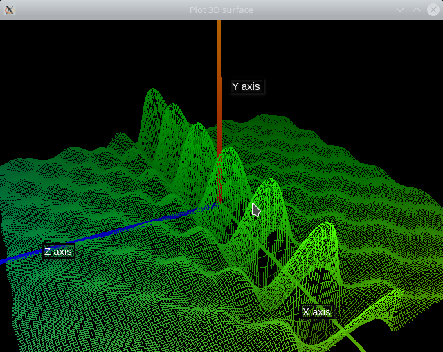
Figure 22: 3D surface wireframe chart of f(x, z)
Code Highlights
Data structures:
struct Position { GLfloat x, y, z;  };
struct Normal   { GLfloat x, y, z;  };
struct Color    { GLfloat r, g, b;  };

struct Vertex   {
    Position position; // Vertex position in space
    Normal   normal;   // Vertex normal vector for illumination (Future use)
    Color    color;    // Vertex color (RGB)
};


// Mesh - set of vertices (position and attributes) that represents
// some surface or solid.
struct Mesh
{
    std::vector<Vertex> vertices{};
    std::vector<GLuint> indices{};
    GLfloat line_width = 1.0;
    GLenum  draw_type;
    GLuint vao = 0, vbo = 0, ibo = 0;

    // Draw mesh using indices
    void draw_indices()
    {
        // Check wheter the mesh was sent to GPU.
        assert( vao != 0 && ibo != 0 );
        // Note: The subroutine glLineWidth is stateful!!
        glLineWidth(line_width);
        glBindVertexArray(vao);
        glDrawElements(draw_type, indices.size(), GL_UNSIGNED_INT, nullptr);
    }

    // Draw mesh using vertices
    void draw_vertices()
    {
        assert( vao != 0 );
        glLineWidth(line_width);
        glBindVertexArray(vao);
        glDrawArrays(draw_type, 0, vertices.size());
    }
};
Subroutine for generating surface mesh:
Mesh generate_surface_wireframe_mesh(
                             float xmin, float xmax
                           , float zmin, float zmax
                           , size_t Nx, size_t Nz
                           , Color color
                           , SurfaceFunction const& function)
{
    assert( xmax > xmin );
    assert( zmax > zmin );
    assert( Nx  != 0 && Nz  != 0 );

    std::cout << " [TRACE] Nx = " << Nx << " ; Nz = " << Nz << '\n';

    Mesh mesh;
    mesh.draw_type = GL_LINES;

    float dx = (xmax - xmin) / Nx;
    float dz = (zmax - zmin) / Nz;

    // Intial allocation for avoiding many dynamic allocations
    mesh.vertices.reserve( Nx * Nz );
    mesh.indices.reserve( 2 * Nx * Nz  );
    float x, y, z, y_h;

    // Draw lines parallel to plane XY
    for(size_t j = 0; j < Nz; j++)
    {   for(size_t i = 0; i < Nx; i++)
        {
            x = xmin + i * dx;
            z = zmin + j * dz;
            y = function(x, z);
            y_h = function(x + dx, z);

            // Draw line segments in planes parallel to plane XY.
            //---------------------------------------------------------------------//
            // Initial vertex of line  segment
            mesh.vertices.push_back( Vertex{ Position{x, y, z}, zero_normal, color } );
            // Final vertex of line segment
            mesh.vertices.push_back( Vertex{ Position{x + dx, y_h, z}, zero_normal, color } );

        }
    }

    for(size_t i = 0; i < Nx; i++)
    {   for(size_t j = 0; j < Nz; j++)
        {
            x = xmin + i * dx;
            z = zmin + j * dz;
            y = function(x, z);
            y_h = function(x, z + dz);

            // Draw line segments in planes parallel to plane YZ.
            mesh.vertices.push_back( Vertex{ Position{x, y, z       }, zero_normal, color } );
            mesh.vertices.push_back( Vertex{ Position{x, y_h, z + dz}, zero_normal, color } );

         }
    }
    return mesh;
}
Vertex shader:
#version 330 core

layout ( location = 0)  in vec3 position;
layout ( location = 1) in vec3 color;

out vec3 out_color;
out vec3 out_coord;
out vec3 out_eye;

uniform vec3 u_eye;  // Cameras's position in space
uniform mat4 u_model;       // Model matrix
uniform mat4 u_view;        // Camera's view matrix
uniform mat4 u_projection;  // Camera's projection matrix


void main()
{
    gl_Position = u_projection * u_view * u_model * vec4(position, 1.0);

    // Forward to fragment shader
    out_coord  = position;
    out_color = color; // vec3(0.56, 0.6, 0.0);
    out_eye = u_eye;
}
Fragment shader:
#version 330

in vec3 out_color;
in vec3 out_coord;
in vec3 out_eye;

void main()
{
    float k;

    if(gl_FrontFacing)
        k = 1.0; // 2.0;
    else
        k = 0.1; // 0.01;

    float factor = distance(out_eye, out_coord) ;

    // Set vertex colors
    vec3 color = (out_coord / 2.0 / factor ) + k * out_color * ( 20.0 / factor ) ;
    // vec3 color =  k * out_color * ( 20.0 / factor ) ;

    // vec3 color = 1.0 / fac + (out_color / 2.0 + 0.5) * k;

    gl_FragColor =  vec4( color , 1.0);
    // gl_FragColor = vec4(0.3, 0.6, 0.0, 1.0);
}
Source code
File: CMakeLists.txt
cmake_minimum_required(VERSION 3.5)
project(OpenGL_3D_Wireframe_Surface_Chart)

set(CMAKE_CXX_STANDARD 17)
set(CMAKE_CXX_STANDARD_REQUIRED ON)
set(CMAKE_VERBOSE_MAKEFILE ON)

#================ GLFW Settings  ===============#

find_package(OpenGL REQUIRED)

include(FetchContent)

# Set GLFW Options before FectchContent_MakeAvailable
set( GLFW_BUILD_EXAMPLES OFF CACHE BOOL  "GLFW lib only" )
set( GLFW_BUILD_TESTS    OFF CACHE BOOL  "GLFW lib only" )
set( GLFW_BUILD_DOCS     OFF CACHE BOOL  "GLFW lib only" )
set( GLFW_BUILD_INSTALL  OFF CACHE BOOL  "GLFW lib only" )

# Donwload GLFW library
FetchContent_Declare(
  glfwlib
  URL   https://github.com/glfw/glfw/releases/download/3.3.2/glfw-3.3.2.zip
)
FetchContent_MakeAvailable(glfwlib)

# Download GLM (OpenGL math library for matrix and vectors transformation)
FetchContent_Declare(
  glm
  URL  https://github.com/g-truc/glm/archive/0.9.8.zip
)
FetchContent_MakeAvailable(glm)
include_directories(${glm_SOURCE_DIR})


# Download pre-compiled GLEW when building under Windows NT OS (x64)
IF(WIN32)
   FetchContent_Declare(
      glew-release
      URL    https://ufpr.dl.sourceforge.net/project/glew/glew/2.1.0/glew-2.1.0-win32.zip
      # https://github.com/nigels-com/glew/archive/glew-2.2.0.zip
   )
   FetchContent_MakeAvailable(glew-release)
   include_directories( ${glew-release_SOURCE_DIR}/include  ${glm_SOURCE_DIR} )
   link_directories(  ${glew-release_SOURCE_DIR}/lib/Release/x64 )

   set( GLEW_LIB_PATH1 ${glew-release_SOURCE_DIR}/lib/Release/x64/glew32.lib )
   set( GLEW_LIB_PATH2 ${glew-release_SOURCE_DIR}/lib/Release/x64/glew32s.lib )
ENDIF()


MACRO(ADD_OPENGL_APP target sources)
   add_executable( ${target} ${sources} )
   message([TRACE] " Add OpenGL executable = ${target} ")

   target_link_libraries( ${target} glfw
                                    OpenGL::GL
                                    ${GLEW_LIB_PATH1}
                                    ${GLEW_LIB_PATH2} )

    IF(MINGW)
        # Statically link against MINGW dependencies
        # for making easier to deploy on other machines.
        target_link_options( ${target} PRIVATE
                                 -static-libgcc
                                 -static-libstdc++
                                 -Wl,-Bstatic,--whole-archive -lwinpthread
                                   -Wl,--no-whole-archive
                                 )
     ENDIF()


     # Copy GLEW DLL shared library to same directory as the executable.
     IF(WIN32)
        add_custom_command(TARGET ${target} POST_BUILD
                       COMMAND ${CMAKE_COMMAND} -E copy_if_different
                       "${glew-release_SOURCE_DIR}/bin/Release/x64/glew32.dll"
                       $<TARGET_FILE_DIR:${target}>)
     ENDIF()
ENDMACRO()

     # ======= T A R G E T S ============================#
     #                                                   #

ADD_OPENGL_APP( draw3d-plot-surface draw3d-plot-surface.cpp )
File: draw3d-plot-surface.cpp
#include <iostream>
#include <string>
#include <sstream>
#include <vector>
#include <array>
#include <cmath>
#include <functional>
#include <thread>

// -------- OpenGL headers ---------//
//
#define GL_GLEXT_PROTOTYPES 1 // Necessary for OpenGL >= 3.0 functions
#define GL3_PROTOTYPES      1 // Necessary for OpenGL >= 3.0 functions

#include <GL/gl.h>
#include <GLFW/glfw3.h>

// #include <GL/glew.h>
#include <GL/glu.h>

// --------- OpenGL Math Librar ------------//
#include <glm/glm.hpp>
#include <glm/gtc/matrix_transform.hpp>
#include <glm/gtc/type_ptr.hpp>
#include <glm/gtx/string_cast.hpp>

// #define GLUT_ENABLED

#if defined(GLUT_ENABLED)
    #include <GL/glut.h>
#endif

#define GL_CHECK(funcall)\
    do { \
        (funcall); \
        GLint error = glGetError();  \
        if(error == GL_NO_ERROR){ break; } \
        std::fprintf(stderr, " [OPENGL ERROR] Error code = %d ; line = %d ; call = '%s'  \n" \
                      , error, __LINE__, #funcall ); \
        abort(); \
    } while(0)

GLFWwindow* make_glfwWindow(int  width, int height, const char* title);

// Compile some  shader
void compile_shader(GLuint m_program, const char* code, GLenum type);

// ------------ Basic Data Structures -----------//
struct Position { GLfloat x, y, z;  };
struct Normal   { GLfloat x, y, z;  };
struct Color    { GLfloat r, g, b;  };

struct Vertex   {
    Position position; // Vertex position in space
    Normal   normal;   // Vertex normal vector for illumination (Future use)
    Color    color;    // Vertex color (RGB)
};

std::ostream& operator<<(std::ostream& os, Vertex const& v)
{
    return os << " Vertex{ x = " << v.position.x << " ; "
              << " y = " << v.position.y << " ; z = " << v.position.z << " } ";
}

// Mesh - set of vertices (position and attributes) that represents
// some surface or solid.
struct Mesh
{
    std::vector<Vertex> vertices{};
    std::vector<GLuint> indices{};
    GLfloat line_width = 1.0;
    GLenum  draw_type;
    GLuint vao = 0, vbo = 0, ibo = 0;

    // Draw mesh using indices
    void draw_indices()
    {
        // Check wheter the mesh was sent to GPU.
        assert( vao != 0 && ibo != 0 );
        // Note: The subroutine glLineWidth is stateful!!
        glLineWidth(line_width);
        glBindVertexArray(vao);
        glDrawElements(draw_type, indices.size(), GL_UNSIGNED_INT, nullptr);
    }

    // Draw mesh using vertices
    void draw_vertices()
    {
        assert( vao != 0 );
        glLineWidth(line_width);
        glBindVertexArray(vao);
        glDrawArrays(draw_type, 0, vertices.size());
    }
};


// Send/upload mesh data to GPU
// attr_position =>> Shader attribute location for vertex position
// attr_color    =>> Shader attribute location for vertex color
void send_mesh( Mesh& mesh , GLint attr_position , GLint attr_color );

constexpr Position origin = { 0.0, 0.0, 0.0};
constexpr Position position_x(float x){ return {x, 0.0, 0.0};  }
constexpr Position position_y(float y){ return {0.0, y, 0.0};  }
constexpr Position position_z(float z){ return {0.0, 0.0, z};  }

constexpr Normal zero_normal = { 0.0, 0.0 , 0.0};
constexpr Color  color_red   = {1.0, 0.0, 0.0};
constexpr Color  color_green = {0.0, 1.0, 0.0};
constexpr Color  color_blue  = {0.0, 0.0, 1.0};

const glm::mat4 matrix_identity = glm::mat4(1.0);


struct Camera
{
    // Current location of camera in world coordinates
    glm::vec3 eye  = { 2.0, 4.0, 5.0 };
    // Direction to where camera is looking at.
    glm::vec3 forward =  {-1.0, 0.0, -1.0 };
    // Current  camera up vector (orientation) - Y axis (default)
    glm::vec3 up = { 0.0, 1.0, 0.0 };

    // Field of view
    float fov_angle = glm::radians(60.0);
    // Aspect ratio
    float aspect   = 1.0;
    float zFar     = 100.0;
    float zNear    = 0.1;

    // ID of shader's view uniform variable - for setting view matrix
    GLint shader_uniform_view = -1;
    // ID of shader's projection uniform variable for setting projection matrix.
    GLint shader_uniform_proj = -1;

    GLint shader_uniform_eye = -1;

    Camera(GLuint uniform_view, GLuint uniform_proj, GLuint uniform_eye, float aspect):
         shader_uniform_view(uniform_view)
       , shader_uniform_proj(uniform_proj)
       , shader_uniform_eye(uniform_eye)
       , aspect(aspect)
    {  update_view();  }

    void update_view()
    {

        // Point to where camera is looking at.
        auto cam_at = this->eye + this->forward;
        // Create View matrix (maps from world-space to camera-space)
        auto Tview = glm::lookAt(eye, cam_at, up);
        // Create projection matrix maps - camera-space to NDC (Normalized Device Coordinates).
        auto Tproj = glm::perspective( fov_angle, aspect, zNear, zFar );
        // Set shader uniform variables.
        glUniformMatrix4fv(shader_uniform_view, 1, GL_FALSE, glm::value_ptr(Tview) );
        glUniformMatrix4fv(shader_uniform_proj, 1, GL_FALSE, glm::value_ptr(Tproj) );
        glUniform3fv(shader_uniform_eye, 1, glm::value_ptr(eye));
    }

    // Rotate around camera's Up vecto.
    void rotate_yaw(float angle)
    {
        // Build quaternion from axis angle
        glm::quat q = glm::angleAxis(glm::radians(angle), this->up);
        // Rotate current forward vector
        forward = forward * q;
        // std::cout << " [FORWARD VECTOR ] " << glm::to_string(forward) << '\n';
        this->update_view();
    }

    // Rotate around camera's pitch axis (X axis) elevate camera view.
    void rotate_pitch(float angle)
    {
        glm::vec3 axis = glm::cross(this->up, this->forward);
        // Build quaternion from axis angle
        glm::quat q = glm::angleAxis(glm::radians(angle), axis);
        forward = q * forward;
        this->update_view();
    }

      // Move at forward vector direction (to where camera is looking at).
    void move_forward(float factor)
    {
        this->eye = this->eye + factor * this->forward;
        this->update_view();
    }
    // Move camera to specific point in the space.
    void set_position(float x, float y, float z)
    {
        this->eye = glm::vec3(x, y, z);
        this->update_view();
    }

    // Set position to where camera is looking at.
    void look_at(const glm::vec3& at)
    {
        this->forward = at - this->eye;
        this->update_view();
    }

};

using SurfaceFunction = std::function<float (float, float)>;

// Nx - Number of points in the Xmin, Xmax interval
// Ny - Number of points in the Ymin, Ymax interval
Mesh generate_surface_wireframe_mesh(
                             float xmin, float xmax
                           , float zmin, float zmax
                           , size_t Nx, size_t Nz
                           , Color color
                           , SurfaceFunction const& function);

int main(int argc, char** argv)
{

    /* Initialize the library */
    if (!glfwInit()){ return -1; }

    #if defined(GLUT_ENABLED)
        glutInit(&argc, argv);
    #endif

    // ====== S H A D E R - C O M P I L A T I O N ====//
    //                                                //

    GLFWwindow* window = make_glfwWindow(640, 480, "Plot 3D surface");

    // Note: The shader source code is at the end of file.
    extern const char* code_vertex_shader;
    extern const char* code_frag_shader;

    GLuint prog = glCreateProgram();
    // Compile shader code
    compile_shader(prog, code_vertex_shader, GL_VERTEX_SHADER  ) ;
    compile_shader(prog, code_frag_shader,   GL_FRAGMENT_SHADER );
    glUseProgram(prog);

    // Get shader uniform variable location for projection matrix
    // See shader code: "uniform mat4 projection;"
    const GLint u_proj  = glGetUniformLocation(prog, "u_projection");
    assert( u_proj >= 0 && "Failed to find u_projection uniform variable" );

    const GLint u_view = glGetUniformLocation(prog, "u_view");
    assert( u_proj >= 0 && "Failed to find u_view uniform variable" );

    // Get shader uniform variable  location for model matrix.
    const GLint u_model  = glGetUniformLocation(prog, "u_model");
    assert( u_model >= 0 && "Failed to find uniform variable" );

    const GLint u_camera_eye = glGetUniformLocation(prog, "u_eye");
    printf(" [TRACE] u_camera_eye = %d \n", u_camera_eye);
    assert( u_camera_eye >= 0 );

    // Get shader attribute location - the function glGetAttribLocation - returns (-1) on error.
    const GLint attr_position = glGetAttribLocation(prog, "position");
    assert( attr_position >= 0 && "Failed to get attribute location" );

    // Get shader attribute of color
    const GLint attr_color = glGetAttribLocation(prog, "color");
    if( attr_color < 0){ std::fprintf(stderr, " [WARNING] Shader color attribute location not found. \n"); };

    glUniformMatrix4fv(u_model, 1, GL_FALSE, glm::value_ptr(matrix_identity) );
    glUniformMatrix4fv(u_proj,  1, GL_FALSE, glm::value_ptr(matrix_identity) );

    // ====== U P L O A D - TO - G P U =========================//
    //                                                          //

    // ----- X, Y, Z axis for visual debugging ----------------
    // X axis (GREEN) ; Y axis (RED); Z axis (BLUE)
    GLuint vao_axis = 0;
    GLuint vbo_axis_vertices = 0;
    GLuint vbo_axis_colors = 0;
    float axis_len = 100.0;


    Mesh mesh_axis{};
    mesh_axis.vertices = {
          // X axis line
          { origin,                  zero_normal,  color_green }
        , { position_x(axis_len),    zero_normal,  color_green }
          // Y axis line
        , { origin,                   zero_normal,  color_red  }
        , { position_y(axis_len),     zero_normal,  color_red  }
          //  Z axis line
        , { origin,                   zero_normal,  color_blue }
        , { position_z(axis_len),     zero_normal,  color_blue }
    };
    mesh_axis.line_width = 10.0;
    mesh_axis.draw_type  = GL_LINES;
    send_mesh(mesh_axis, attr_position, attr_color);


    Mesh mesh_surface = generate_surface_wireframe_mesh(
                              -20, +20.0  // Xmax, Xmin
                            , -20, +20.0  // Zmax, Zmin
                            ,  200, 200   // Nx, Nz     => Number of points on X and Z axis
                            , color_green // Surface wireframe color
                            // , [&](float x, float z){ return 25.0 - x * x - z * z ;}
                            , [&](float x, float z){ return 10.0 * sin(x) * sin(z) / z  ; }
                        );
    mesh_surface.line_width = 0.25;
    mesh_surface.draw_type  = GL_LINES;
    send_mesh(mesh_surface, attr_position, attr_color);

    // ============== Set Shader Uniform Variables =============//
    //                                                          //

    int width, height;
    glfwGetWindowSize(window, &width, &height);
    // Window aspect ratio
    float aspect = static_cast<float>(width) / height;

    // Set projection matrix uniform variable
    // glUniformMatrix4fv(u_proj, 1, GL_FALSE, glm::value_ptr(identity) );

    Camera camera(u_view, u_proj, u_camera_eye, width / height);
    camera.set_position(-23.0, 21.0, -22.0);
    camera.look_at({0.0, 0.0, 0.0});

    //  ======= R E N D E R  - L O O P ============//
    //                                             //
    while ( !glfwWindowShouldClose(window) )
    {
        glClear(GL_COLOR_BUFFER_BIT  | GL_DEPTH_BUFFER_BIT);

        // ====== BEGIN RENDERING ============//

            // Draw axis lines
            mesh_axis.draw_vertices();

            // Draw surface
            mesh_surface.draw_vertices();
            // mesh_surface.draw_indices();


        // ====== END RENDERING ==============//

        /* Swap front and back buffers */
        glfwSwapBuffers(window);
        /* Poll for and process events */
        glfwWaitEvents();

        if( glfwGetKey(window, 'Q' ) == GLFW_PRESS )
        {
             std::cout << " [TRACE] User typed Q =>> Shutdown program. Ok. " << '\n';
             break;
        }

        // Move camera to direction to where it is looking at.
        if( glfwGetKey(window, GLFW_KEY_UP ) == GLFW_PRESS    ){ camera.move_forward(+0.5);  }
        if( glfwGetKey(window, GLFW_KEY_DOWN ) == GLFW_PRESS  ){ camera.move_forward(-0.5);  }

        // Rotate around its Y axis
        if( glfwGetKey(window, GLFW_KEY_RIGHT) == GLFW_PRESS  ){ camera.rotate_yaw(+5.0);   }
        if( glfwGetKey(window, GLFW_KEY_LEFT ) == GLFW_PRESS  ){ camera.rotate_yaw(-5.0);   }

        // Rotate camera around its local X axis
        if( glfwGetKey(window, 'S') == GLFW_PRESS ){ camera.rotate_pitch(+5.0); }
        if( glfwGetKey(window, 'D') == GLFW_PRESS ){ camera.rotate_pitch(-5.0); }

        // Reset camera - look at origin
        if( glfwGetKey(window, 'R' ) == GLFW_PRESS  )
        {
            camera.set_position(4.0, 3.0, 2.5);
            camera.look_at( {0.0, 0.0, 0.0} );
        }

    }

    glfwTerminate();
    return 0;

} // --- End of main() -----//


// ---------- S H A D E R - P R O G R A M S  -------------------------//
//

// Minimal vertex shader =>> Runs on the GPU and processes each vertex.
const char* code_vertex_shader = R"(
    #version 330 core

    layout ( location = 0)  in vec3 position;
    layout ( location = 1) in vec3 color;

    out vec3 out_color;
    out vec3 out_coord;
    out vec3 out_eye;

    uniform vec3 u_eye;  // Cameras's position in space
    uniform mat4 u_model;       // Model matrix
    uniform mat4 u_view;        // Camera's view matrix
    uniform mat4 u_projection;  // Camera's projection matrix


    void main()
    {
        gl_Position = u_projection * u_view * u_model * vec4(position, 1.0);

        // Forward to fragment shader
        out_coord  = position;
        out_color = color; // vec3(0.56, 0.6, 0.0);
        out_eye = u_eye;
    }

)";

// Fragment shader source code
const char* code_frag_shader = R"(
    #version 330

    in vec3 out_color;
    in vec3 out_coord;
    in vec3 out_eye;

    void main()
    {
        float k;

        if(gl_FrontFacing)
            k = 1.0; // 2.0;
        else
            k = 0.1; // 0.01;

        float factor = distance(out_eye, out_coord) ;

        // Set vertex colors
        vec3 color = (out_coord / 2.0 / factor ) + k * out_color * ( 20.0 / factor ) ;
        // vec3 color =  k * out_color * ( 20.0 / factor ) ;

        // vec3 color = 1.0 / fac + (out_color / 2.0 + 0.5) * k;

        gl_FragColor =  vec4( color , 1.0);
        // gl_FragColor = vec4(0.3, 0.6, 0.0, 1.0);
    }
)";


    // ====== I M P L E M E N T A T I O N S ==========//

GLFWwindow*
make_glfwWindow(int  width, int height, const char* title)
{

    glfwSetErrorCallback([](int error, const char* description)
                         { std::fprintf( stderr, " [GLFW ERROR] Error = %d ; Description = %s \n"
                                        , error, description);
                         });

    GLFWwindow* window = glfwCreateWindow(width, height, title, NULL, NULL);
    assert( window != nullptr && "Failed  to create Window");

    // OpenGL context
    glfwMakeContextCurrent(window);
    // Pain whole screen as black - dark screen colors are better
    // for avoding eye strain due long hours staring on monitor.
    glClearColor(0.0f, 0.0f, 0.0f, 1.0f);

    // Set - OpenGL Core Profile - version 3.3
    GL_CHECK( glfwWindowHint(GLFW_CONTEXT_VERSION_MAJOR, 3) );
    GL_CHECK( glfwWindowHint(GLFW_CONTEXT_VERSION_MINOR, 3) );
    GL_CHECK( glfwWindowHint(GLFW_OPENGL_PROFILE, GLFW_OPENGL_CORE_PROFILE) );

    GL_CHECK( glEnable(GL_COLOR_MATERIAL) );
    GL_CHECK( glEnable(GL_DEPTH_TEST)     );
    GL_CHECK( glEnable(GL_BLEND)          );

    return window;
}

void compile_shader(GLuint m_program, const char* code, GLenum type)
{
    GLint shader_id = glCreateShader( type );
    glShaderSource(shader_id, 1, &code, nullptr);
    glCompileShader(shader_id);
    GLint is_compiled = GL_FALSE;
    // Check shader compilation result
    glGetShaderiv(shader_id, GL_COMPILE_STATUS, &is_compiled);
    // If there is any shader compilation result,
    // print the error message.
    if( is_compiled == GL_FALSE)
    {
        GLint length;
        glGetShaderiv(shader_id, GL_INFO_LOG_LENGTH, &length);
        assert( length > 0 );

        std::string out(length + 1, 0x00);
        GLint chars_written;
        glGetShaderInfoLog(shader_id, length, &chars_written, out.data());
        std::cerr << " [SHADER ERROR] = " << out << '\n';
        // Abort the exection of current process.
        std::abort();
    }

    glAttachShader(m_program, shader_id);
    glDeleteShader(shader_id);
    glLinkProgram(m_program);
    GLint link_status = GL_FALSE;
    glGetProgramiv(m_program, GL_LINK_STATUS, &link_status);
    assert( link_status != GL_FALSE );
    // glUseProgram(m_program);
}

//  Send  mesh data to GPU ----//
void send_mesh( Mesh& mesh , GLint attr_position , GLint attr_color   )
{
    GLuint& vao = mesh.vao;
    GLuint& vbo = mesh.vbo;
    GLuint& ibo = mesh.ibo;

    // ------------- Upload vertices --------------//

    // Generate and bind current VAO (Vertex Array Object)
    if(vao == 0){ glGenVertexArrays(1, &vao); }
    glBindVertexArray(vao);
    // Generate and bind current VBO (Vertex Buffer Object)
    glGenBuffers(1, &vbo);
    glBindBuffer(GL_ARRAY_BUFFER, vbo);
    // Upload data to current VBO buffer in GPU
    glBufferData(GL_ARRAY_BUFFER, mesh.vertices.size() * sizeof(Vertex)
                , mesh.vertices.data(), GL_STATIC_DRAW);

    glEnableVertexAttribArray(attr_position);
    glEnableVertexAttribArray(attr_color);

    // Set data layout - how data will be interpreted.
    // => Each vertex has 2 coordinates.
    glVertexAttribPointer( attr_position, 3, GL_FLOAT, GL_FALSE, sizeof(Vertex), nullptr);

    glVertexAttribPointer( attr_color, 3, GL_FLOAT, GL_FALSE, sizeof(Vertex)
                           // Offset to color member variable in class Vertex2D
                          , reinterpret_cast<void*>( offsetof(Vertex, color) )
                          );

    // -------- Upload indices ----------------------//
    //
    if (!mesh.indices.empty())
    {
        glBindVertexArray(vao);
        glGenBuffers(1, &ibo);
        glBindBuffer(GL_ELEMENT_ARRAY_BUFFER, ibo);
        glBufferData(GL_ELEMENT_ARRAY_BUFFER, mesh.indices.size() * sizeof(GLuint)
                     , mesh.indices.data(), GL_STATIC_DRAW );
    }

    // ------ Disable Global state set by this function -----//
    // Unbind VAO
    glBindVertexArray(0);
    // Unbind VBO
    glBindBuffer(GL_ARRAY_BUFFER, 0);
    // Unbind IBO
    glBindBuffer( GL_ELEMENT_ARRAY_BUFFER, 0);
    // Disable current shader attribute
    glDisableVertexAttribArray(attr_position);
    glDisableVertexAttribArray(attr_color);

}


Mesh generate_surface_wireframe_mesh(
                             float xmin, float xmax
                           , float zmin, float zmax
                           , size_t Nx, size_t Nz
                           , Color color
                           , SurfaceFunction const& function)
{
    assert( xmax > xmin );
    assert( zmax > zmin );
    assert( Nx  != 0 && Nz  != 0 );

    std::cout << " [TRACE] Nx = " << Nx << " ; Nz = " << Nz << '\n';

    Mesh mesh;
    mesh.draw_type = GL_LINES;

    float dx = (xmax - xmin) / Nx;
    float dz = (zmax - zmin) / Nz;

    // Intial allocation for avoiding many dynamic allocations
    mesh.vertices.reserve( Nx * Nz );
    mesh.indices.reserve( 2 * Nx * Nz  );
    float x, y, z, y_h;

    // Draw lines parallel to plane XY
    for(size_t j = 0; j < Nz; j++)
    {   for(size_t i = 0; i < Nx; i++)
        {
            x = xmin + i * dx;
            z = zmin + j * dz;
            y = function(x, z);
            y_h = function(x + dx, z);

            // Draw line segments in planes parallel to plane XY.
            mesh.vertices.push_back( Vertex{ Position{x, y, z}, zero_normal, color } );
            mesh.vertices.push_back( Vertex{ Position{x + dx, y_h, z}, zero_normal, color } );

        }
    }

    for(size_t i = 0; i < Nx; i++)
    {   for(size_t j = 0; j < Nz; j++)
        {
            x = xmin + i * dx;
            z = zmin + j * dz;
            y = function(x, z);
            y_h = function(x, z + dz);

            // Draw line segments in planes parallel to plane YZ.
            mesh.vertices.push_back( Vertex{ Position{x, y, z       }, zero_normal, color } );
            mesh.vertices.push_back( Vertex{ Position{x, y_h, z + dz}, zero_normal, color } );

         }
    }
    return mesh;
}
1.26 3D - 3D model loading with illumination
This sample code loads 3D meshes from obj file with help from tinyObjLoader library and draws the loaded meshes (3D models) triangles using ambient and diffuse light.
Libraries used:
- glfw
- Library for Window Abstraction and dealing with OpenGL context.
- GLM math library
- Computer graphics linear algebra library
- Glew
- Library for loading OpenGL function pointers. It is used only on Windows in Pre-compiled form due to the difficulty to build the library from source as it requires perl.
- tinyobjloader
- Library for loading 3D meshes from Obj files.
- cmrc - Cmake Resource Compiler
- Single-file CMake library for embedding files in the executable, shader scripts and 3D models. This Cmake utility makes easier to distribute the binary, since just a single file is distributed or deployed and the application does not have to deal with file system path and relative path.
See also:
Screenshot
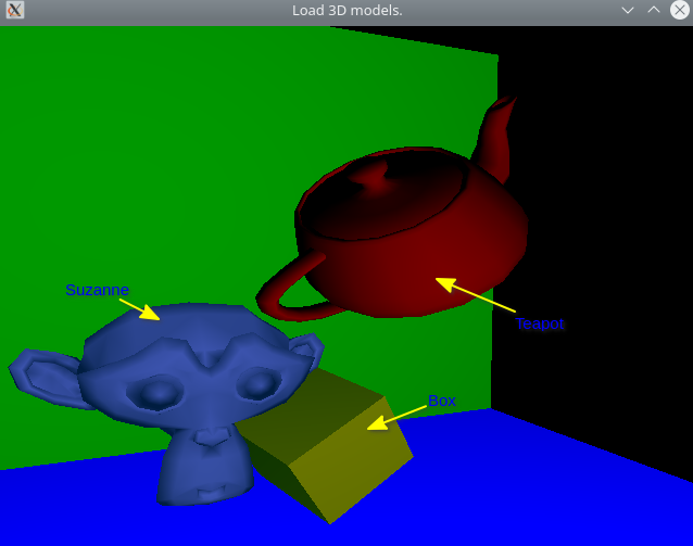
Files
File: CMakeLists.txt
cmake_minimum_required(VERSION 3.5) project( OpenGL_3D_Model_Loader ) set(CMAKE_CXX_STANDARD 17) set(CMAKE_CXX_STANDARD_REQUIRED ON) set(CMAKE_VERBOSE_MAKEFILE ON) #================ GLFW Settings ===============# find_package(OpenGL REQUIRED) include(FetchContent) # Set GLFW Options before FectchContent_MakeAvailable set( GLFW_BUILD_EXAMPLES OFF CACHE BOOL "GLFW lib only" ) set( GLFW_BUILD_TESTS OFF CACHE BOOL "GLFW lib only" ) set( GLFW_BUILD_DOCS OFF CACHE BOOL "GLFW lib only" ) set( GLFW_BUILD_INSTALL OFF CACHE BOOL "GLFW lib only" ) # Donwload GLFW library FetchContent_Declare( glfwlib URL https://github.com/glfw/glfw/releases/download/3.3.2/glfw-3.3.2.zip ) FetchContent_MakeAvailable(glfwlib) # Download GLM (OpenGL math library for matrix and vectors transformation) FetchContent_Declare( glm URL https://github.com/g-truc/glm/archive/0.9.8.zip ) FetchContent_MakeAvailable(glm) include_directories( ${glm_SOURCE_DIR} ) FetchContent_Declare( tinyobjloader URL https://github.com/tinyobjloader/tinyobjloader/archive/v2.0.0rc8.zip ) FetchContent_MakeAvailable(tinyobjloader) # Download pre-compiled GLEW when building under Windows NT OS (x64) IF(WIN32) FetchContent_Declare( glew-release URL https://ufpr.dl.sourceforge.net/project/glew/glew/2.1.0/glew-2.1.0-win32.zip # https://github.com/nigels-com/glew/archive/glew-2.2.0.zip ) FetchContent_MakeAvailable(glew-release) include_directories( ${glew-release_SOURCE_DIR}/include ${glm_SOURCE_DIR} ) link_directories( ${glew-release_SOURCE_DIR}/lib/Release/x64 ) set( GLEW_LIB_PATH1 ${glew-release_SOURCE_DIR}/lib/Release/x64/glew32.lib ) set( GLEW_LIB_PATH2 ${glew-release_SOURCE_DIR}/lib/Release/x64/glew32s.lib ) ENDIF() ## Fetch Cmake-Resource Compiler file(DOWNLOAD "https://raw.githubusercontent.com/vector-of-bool/cmrc/master/CMakeRC.cmake" "${CMAKE_BINARY_DIR}/CMakeRC.cmake") include("${CMAKE_BINARY_DIR}/CMakeRC.cmake") MACRO(ADD_OPENGL_APP target sources) add_executable( ${target} ${sources} ) message([TRACE] " Add OpenGL executable = ${target} ") target_link_libraries( ${target} glfw OpenGL::GL ${GLEW_LIB_PATH1} ${GLEW_LIB_PATH2} ) IF(MINGW) # Statically link against MINGW dependencies # for making easier to deploy on other machines. target_link_options( ${target} PRIVATE -static-libgcc -static-libstdc++ -Wl,-Bstatic,--whole-archive -lwinpthread -Wl,--no-whole-archive ) ENDIF() # Copy GLEW DLL shared library to same directory as the executable. IF(WIN32) add_custom_command(TARGET ${target} POST_BUILD COMMAND ${CMAKE_COMMAND} -E copy_if_different "${glew-release_SOURCE_DIR}/bin/Release/x64/glew32.dll" $<TARGET_FILE_DIR:${target}>) ENDIF() ENDMACRO() # Download Suzanne 3D model file(DOWNLOAD https://raw.githubusercontent.com/alecjacobson/common-3d-test-models/master/data/suzanne.obj ${CMAKE_CURRENT_SOURCE_DIR}/suzanne.obj ) # Download Teapot 3D model file(DOWNLOAD https://raw.githubusercontent.com/kevinroast/phoria.js/master/teapot.obj ${CMAKE_CURRENT_SOURCE_DIR}/teapot.obj ) # ----------- T A R G E T S ---------------------------$ ADD_OPENGL_APP( model-loader model-loader.cpp ) # Define resourse files to be embedded in the executable (model-loader) cmrc_add_resource_library( model-loader-resources NAMESPACE resource ./model_loader_vshader.glsl ./model_loader_fshader.glsl ./suzanne.obj ./cube.obj ./teapot.obj ) # Append resources to the executable target_link_libraries( model-loader model-loader-resources tinyobjloader )
File: model_loader_vshader.glsl / Vertex Shader
// Vertex Shader Source Code #version 330 core layout ( location = 0 ) in vec3 position; layout ( location = 1 ) in vec3 normal; layout ( location = 2 ) in vec3 color; uniform mat4 u_model; // Model matrix uniform mat4 u_view; // Camera's view matrix uniform mat4 u_projection; // Camera's projection matrix uniform mat4 u_normal; // Normal matrix (transpose of view-model inverse) varying highp vec4 out_color; varying highp vec4 out_light; varying vec3 mv_normal, mv_view, mv_position; // ------ Pre-defined colors for debugging -----// void main() { mat4 model_view = u_view * u_model; // Should be computed at the application-side /// mat4 normal_mat = transpose(inverse(model_view)); // Convert normal to eye space coordinates (aka camera coordinates) // mv_normal = normalize( ( normal_mat * vec4(normal, 0.0)).xyz ); mv_normal = normalize( ( u_normal * vec4(normal, 0.0)).xyz ); // Set #if argument to 1 in order to debug the normal #if 0 vec3 _position = position + abs(mv_normal); #else vec3 _position = position; #endif gl_Position = u_projection * u_view * u_model * vec4(_position, 1.0); // ------------- Lighting -----------------------// // Vertex coordinate in eye space (camera-space) mv_position = ( model_view * vec4(position, 1.0) ).xyz; // out_light = vec4(light, 1.0); out_color = vec4(color, 1.0); }
File: model_loader_fshader.glsl / Fragment Shader
// Fragment Shader Source Code #version 330 precision mediump float; varying highp vec4 out_color; varying highp vec4 out_light; varying vec3 mv_normal, mv_light, mv_view, mv_position; uniform vec3 u_product_diffuse; uniform vec3 u_light_position; uniform vec3 u_product_ambient; // Specular coefficient float spec = 10.0; uniform vec3 u_product_specular; const vec3 color_red = vec3(1.0, 0.0, 0.0); const vec3 color_green = vec3(0.0, 1.0, 0.0); void main() { vec3 _normal = mv_normal; //;normalize( mv_normal ); // vec3 light_direction = normalize(vec3(100, 100, 100)); vec3 light_direction = normalize( u_light_position - mv_position ); float lambert = max( dot(_normal, light_direction), -1.0); vec3 light_ambient = u_product_ambient; vec3 light_diffuse = u_product_diffuse * lambert; // View vector for specular light vec3 _view = normalize( mv_view); // Halfway vector vec3 H = normalize( light_direction + _view ); vec3 light_specular = pow( max(dot(H, _normal), 0.0), spec) * u_product_specular; vec4 light = vec4(light_ambient + light_diffuse, 1.0); // vec4 light = vec4(light_ambient + light_diffuse + light_specular, 1.0); // gl_FragColor = out_light ; gl_FragColor = light * out_color; }
File: cube.obj / Cube 3D model Obj file
# cube.obj # mtllib cube.mtl o cube v -0.500000 -0.500000 0.500000 v 0.500000 -0.500000 0.500000 v -0.500000 0.500000 0.500000 v 0.500000 0.500000 0.500000 v -0.500000 0.500000 -0.500000 v 0.500000 0.500000 -0.500000 v -0.500000 -0.500000 -0.500000 v 0.500000 -0.500000 -0.500000 vt 0.000000 0.000000 vt 1.000000 0.000000 vt 0.000000 1.000000 vt 1.000000 1.000000 vn 0.000000 0.000000 1.000000 vn 0.000000 1.000000 0.000000 vn 0.000000 0.000000 -1.000000 vn 0.000000 -1.000000 0.000000 vn 1.000000 0.000000 0.000000 vn -1.000000 0.000000 0.000000 g cube usemtl cube s 1 f 1/1/1 2/2/1 3/3/1 f 3/3/1 2/2/1 4/4/1 s 2 f 3/1/2 4/2/2 5/3/2 f 5/3/2 4/2/2 6/4/2 s 3 f 5/4/3 6/3/3 7/2/3 f 7/2/3 6/3/3 8/1/3 s 4 f 7/1/4 8/2/4 1/3/4 f 1/3/4 8/2/4 2/4/4 s 5 f 2/1/5 8/2/5 4/3/5 f 4/3/5 8/2/5 6/4/5 s 6 f 7/1/6 1/2/6 5/3/6 f 5/3/6 1/2/6 3/4/6
File: model-loader.cpp
#include <iostream> #include <string> #include <sstream> #include <vector> #include <array> #include <cmath> #include <functional> #include <thread> // -------- OpenGL headers ---------// // #define GL_GLEXT_PROTOTYPES 1 // Necessary for OpenGL >= 3.0 functions #define GL3_PROTOTYPES 1 // Necessary for OpenGL >= 3.0 functions #if defined(_WIN32) #include <windows.h> #include <GL/glew.h> #endif #include <GL/gl.h> #include <GLFW/glfw3.h> // #include <GL/glew.h> #include <GL/glu.h> // #include <GL/glut.h> // --------- OpenGL Math Librar ------------// #include <glm/glm.hpp> #include <glm/gtc/matrix_transform.hpp> #include <glm/gtc/type_ptr.hpp> #include <glm/gtx/string_cast.hpp> #include <glm/gtx/io.hpp> #include <tiny_obj_loader.h> #include <cmrc/cmrc.hpp> CMRC_DECLARE(resource); struct Position { GLfloat x, y, z; }; struct Normal { GLfloat x, y, z; }; struct Color { GLfloat r, g, b; }; struct Vertex { Position position; // Vertex position in space Normal normal; // Vertex normal vector for illumination (Future use) Color color; // Vertex color (RGB) }; // Mesh - set of vertices (position and attributes) that represents // some surface or solid. struct Mesh { std::vector<Vertex> vertices{}; std::vector<GLuint> indices{}; GLfloat line_width = 1.0; GLenum draw_type; GLuint vao = 0, vbo = 0, ibo = 0; // Draw mesh using indices void draw_indices() { // Check wheter the mesh was sent to GPU. assert( vao != 0 && ibo != 0 ); // Note: The subroutine glLineWidth is stateful!! glLineWidth(line_width); glBindVertexArray(vao); glDrawElements(draw_type, indices.size(), GL_UNSIGNED_INT, nullptr); } // Draw mesh using vertices void draw_vertices() { assert( vao != 0 ); glLineWidth(line_width); glBindVertexArray(vao); glDrawArrays(draw_type, 0, vertices.size()); } }; GLFWwindow* make_glfwWindow(int width, int height, const char* title); void compile_shader(GLuint m_program, const char* code, GLenum type); void send_mesh( Mesh& mesh , GLint attr_position , GLint attr_normal, GLint attr_color); // Load mesh data from obj file, often generated by tools such as Blender or 3D studio max. Mesh load_model(const std::string& file, const Color& color); void set_uniform_matrix(GLint uniform, glm::mat4 const& m) { glUniformMatrix4fv(uniform, 1, GL_FALSE, glm::value_ptr(m) ); } // Get shader uniform location and check return status code. GLint shader_uniform(GLuint program, const char* name); // Get shader attribute location and return status code. GLint shader_attr(GLint program, const char* name); // Get content of resource file, embedded in the executable file, as string. // Requires: #include <cmrc/cmrc.hpp> std::string get_resource(std::string file_name); constexpr Normal zero_normal = { 0.0, 0.0 , 0.0}; constexpr Color color_red = {1.0, 0.0, 0.0}; constexpr Color color_green = {0.0, 1.0, 0.0}; constexpr Color color_blue = {0.0, 0.0, 1.0}; constexpr Color color_gold = {1.0, 0.843, 0.0}; const glm::mat4 matrix_identity = glm::mat4(1.0); struct Camera { // Current location of camera in world coordinates glm::vec3 eye = { 2.0, 4.0, 5.0 }; // Direction to where camera is looking at. glm::vec3 forward = glm::normalize(glm::vec3{-1.0, 0.0, -1.0 }); // Current camera up vector (orientation) - Y axis (default) glm::vec3 up = { 0.0, 1.0, 0.0 }; // Field of view float fov_angle = glm::radians(60.0); // Aspect ratio float aspect = 1.0; float zFar = 100.0; float zNear = 0.1; // ID of shader's view uniform variable - for setting view matrix GLint shader_uniform_view = -1; // ID of shader's projection uniform variable for setting projection matrix. GLint shader_uniform_proj = -1; Camera(GLuint uniform_view, GLuint uniform_proj, GLfloat aspect): shader_uniform_view(uniform_view) , shader_uniform_proj(uniform_proj) , aspect(aspect) { update_view(); } void update_view() { // Point to where camera is looking at. auto cam_at = this->eye + this->forward; std::cerr << " [CAMERA] Camera coordinate (eye) = " << eye << '\n'; std::cerr << " [CAMERA] Looking at direction (forward) = " << forward << '\n'; // Create View matrix (maps from world-space to camera-space) auto Tview = glm::lookAt(eye, cam_at, up); // Create projection matrix maps - camera-space to NDC (Normalized Device Coordinates). auto Tproj = glm::perspective( fov_angle, aspect, zNear, zFar ); // Set shader uniform variables. glUniformMatrix4fv(shader_uniform_view, 1, GL_FALSE, glm::value_ptr(Tview) ); glUniformMatrix4fv(shader_uniform_proj, 1, GL_FALSE, glm::value_ptr(Tproj) ); } // Compute projection matrix glm::mat4 get_proj() { return glm::perspective( fov_angle, aspect, zNear, zFar ); } // Compute view matrix glm::mat4 get_view() { // Point to where camera is looking at. auto cam_at = this->eye + this->forward; auto Tview = glm::lookAt(eye, cam_at, up); return Tview; } // Compute normal view matrix for illumination glm::mat4 normal_view(glm::mat4 const& model) { return glm::transpose( glm::inverse( this->get_view() * model ) ); } // Rotate around camera's Up vecto. void rotate_yaw(float angle) { // Build quaternion from axis angle glm::quat q = glm::angleAxis(glm::radians(angle), this->up); // Rotate current forward vector forward = forward * q; // std::cout << " [FORWARD VECTOR ] " << glm::to_string(forward) << '\n'; this->update_view(); } // Rotate around camera's pitch axis (X axis) elevate camera view. void rotate_pitch(float angle) { glm::vec3 axis = glm::cross(this->up, this->forward); // Build quaternion from axis angle glm::quat q = glm::angleAxis(glm::radians(angle), axis); forward = q * forward; this->update_view(); } // Move at forward vector direction (to where camera is looking at). void move_forward(float factor) { this->eye = this->eye + factor * this->forward; this->update_view(); } // Move camera to specific point in the space. void set_position(float x, float y, float z) { this->eye = glm::vec3(x, y, z); this->update_view(); } // Set position to where camera is looking at. void look_at(const glm::vec3& at) { this->forward = glm::normalize(at - this->eye); this->update_view(); } }; // Create mesh for plane (represented by a square) on origin Mesh make_plane_mesh(float side, glm::vec3 const& VA, glm::vec3 const& VB , Normal const& normal, Color const& color) { glm::vec3 B = side * VA, C = side * VB, D = B + C; Position pA = {0, 0, 0}, pB = {B[0], B[1], B[2]}, pC = {C[0], C[1], C[2]}, pD = {D[0], D[1], D[2]} ; Mesh mesh_plane; mesh_plane.draw_type = GL_TRIANGLES; mesh_plane.line_width = 1.0; mesh_plane.vertices = { // ----- Triagle 1 ------------// { pA, normal, color },{ pB, normal, color }, { pC, normal, color } // ----- Triangle 2 -------------// , { pB, normal, color }, { pC, normal, color } , Vertex{ pD, normal, color } }; return mesh_plane; } int main(int argc, char** argv) { // glutInit(&argc, argv); if (!glfwInit()){ return -1; } GLFWwindow* window = make_glfwWindow(640, 480, "Load 3D models. "); // ====== S H A D E R - C O M P I L A T I O N ====// // // // Note: The shader source code is at the end of file. extern const char* code_vertex_shader; extern const char* code_frag_shader; GLuint prog = glCreateProgram(); std::string vertex_shader = get_resource("/model_loader_vshader.glsl"); std::string fragment_shader = get_resource("/model_loader_fshader.glsl"); // Compile shader code compile_shader(prog, vertex_shader.c_str(), GL_VERTEX_SHADER ) ; compile_shader(prog, fragment_shader.c_str(), GL_FRAGMENT_SHADER ); glUseProgram(prog); const GLint attr_position = shader_attr(prog, "position"); const GLint attr_normal = shader_attr(prog, "normal"); const GLint attr_color = shader_attr(prog, "color"); const GLint u_proj = shader_uniform(prog, "u_projection"); const GLint u_view = shader_uniform(prog, "u_view"); const GLint u_model = shader_uniform(prog, "u_model"); const GLint u_normal = shader_uniform(prog, "u_normal"); const GLint u_product_ambient = shader_uniform(prog, "u_product_ambient"); const GLint u_product_diffuse = shader_uniform(prog, "u_product_diffuse"); const GLint u_product_specular = shader_uniform(prog, "u_product_specular"); const GLint u_light_position = shader_uniform(prog, "u_light_position"); set_uniform_matrix(u_proj, matrix_identity); set_uniform_matrix(u_view, matrix_identity); set_uniform_matrix(u_model, matrix_identity); set_uniform_matrix(u_normal, matrix_identity); // Ambient light RGB colors glm::vec3 La = {0.0, 1.0, 0.5}; // Diffuse light RGB colors glm::vec3 Ld = {0.6, 0.4, 0.9}; // Specular light RGB colors glm::vec3 Ls = {1.0, 1.0, 1.0}; // ---- Material coefficients ------// glm::vec3 ka = {0.5, 0.2, 1.0}; glm::vec3 kd = {0.8, 1.0, 1.0}; glm::vec3 ks = {0.4, 0.3, 0.2}; glm::vec3 light_position = { 1.0, 1.0, 1.0 }; std::cout << " [TRACE] Ambient =>> ka * La = " << (ka * La) << '\n'; std::cout << " [TRACE] Diffuse =>> kd * Ld = " << (kd * Ld) << '\n'; // Note: The product ka * La is an element-wise product. // It is not a dot product or cross product. glUniform3fv(u_light_position, 1, glm::value_ptr( light_position ) ); glUniform3fv(u_product_ambient, 1, glm::value_ptr( ka * La )); glUniform3fv(u_product_diffuse, 1, glm::value_ptr( kd * Ld )); glUniform3fv(u_product_specular, 1, glm::value_ptr( ks * Ls )); Mesh mesh_planeXZ = make_plane_mesh( 10.0, glm::vec3{1.0, 0.0, 0.0} , glm::vec3{0.0, 0.0, 1.0}, Normal{0.0, 1.0, 0.0}, color_blue ); send_mesh(mesh_planeXZ, attr_position, attr_normal, attr_color); Mesh mesh_planeXY = make_plane_mesh( 10.0, glm::vec3{0.0, 1.0, 0.0} , glm::vec3{1.0, 0.0, 0.0}, Normal{0.0, 0.0, 1.0}, color_green ); send_mesh(mesh_planeXY, attr_position, attr_normal, attr_color); Mesh mesh_suzanne = load_model("/suzanne.obj", Color{0.51, 0.56, 0.50}); send_mesh(mesh_suzanne, attr_position, attr_normal, attr_color); glm::mat4 transform_suzanne = matrix_identity; transform_suzanne = glm::translate( transform_suzanne, -glm::vec3( -1.182, 1.306, 3.573) ); transform_suzanne = glm::translate( transform_suzanne, +glm::vec3( 4.0, 3.0, 5.0) ); // model_matrix = glm::rotate( model_matrix, glm::radians(45.0f), glm::vec3(0, 0, 1)); Mesh mesh_cube = load_model("/cube.obj", color_gold); send_mesh(mesh_cube, attr_position, attr_normal, attr_color); glm::mat4 transform_cube = matrix_identity; transform_cube = glm::translate( transform_cube, glm::vec3(4.0, 2.0, 5.0) ); transform_cube = glm::rotate( transform_cube, glm::radians(35.0f), glm::vec3(1.0, 1.0, 2.0) ); transform_cube = glm::scale( transform_cube, glm::vec3(1.2, 1.2, 1.2)); Mesh mesh_teapot = load_model("/teapot.obj", color_red); send_mesh(mesh_teapot, attr_position, attr_normal, attr_color); glm::mat4 transform_teapot = matrix_identity; transform_teapot = glm::translate( transform_teapot, glm::vec3(5.0, 5.0, 5.0) ); transform_teapot = glm::rotate( transform_teapot, glm::radians(50.0f), glm::vec3(3.0, 1.0, 5.0) ); transform_teapot = glm::scale( transform_teapot, glm::vec3(1.0 / 8.0, 1.0 / 8.0, 1.0 / 8.0)); int width, height; glfwGetWindowSize(window, &width, &height); // Window aspect ratio float aspect = static_cast<float>(width) / height; // Set projection matrix uniform variable // glUniformMatrix4fv(u_proj, 1, GL_FALSE, glm::value_ptr(identity) ); Camera camera(u_view, u_proj, width / height); camera.set_position(5.236, 4.078, 11.610); camera.look_at( { 4.0, 1.4, 5.166} ); // Set model matrix and update the normal matrix for // scene illumination calculations. auto set_model_matrix = [&camera, u_normal, u_model](const glm::mat4& model_transform) { set_uniform_matrix(u_model, model_transform); glm::mat4 normal_matrix = glm::transpose( glm::inverse(camera.get_view() * model_transform) ); set_uniform_matrix(u_normal, normal_matrix); }; // ======= R E N D E R - L O O P ============// // // while ( !glfwWindowShouldClose(window) ) { glClear(GL_COLOR_BUFFER_BIT | GL_DEPTH_BUFFER_BIT); // ====== BEGIN RENDERING ============// // set_uniform_matrix(u_model, matrix_identity); set_model_matrix(matrix_identity); mesh_planeXZ.draw_vertices(); // set_uniform_matrix(u_model, matrix_identity); set_model_matrix(matrix_identity); mesh_planeXY.draw_vertices(); set_uniform_matrix(u_model, transform_suzanne); mesh_suzanne.draw_vertices(); set_uniform_matrix(u_model, transform_cube); mesh_cube.draw_vertices(); set_uniform_matrix(u_model, transform_teapot); mesh_teapot.draw_vertices(); // ====== END RENDERING ==============// // Move camera to direction to where it is looking at. if( glfwGetKey(window, GLFW_KEY_UP ) == GLFW_PRESS ){ camera.move_forward(+2.0); } if( glfwGetKey(window, GLFW_KEY_DOWN ) == GLFW_PRESS ){ camera.move_forward(-2.0); } // Rotate around its Y axis if( glfwGetKey(window, GLFW_KEY_RIGHT) == GLFW_PRESS ){ camera.rotate_yaw(+5.0); } if( glfwGetKey(window, GLFW_KEY_LEFT ) == GLFW_PRESS ){ camera.rotate_yaw(-5.0); } // Rotate camera around its local X axis if( glfwGetKey(window, 'S') == GLFW_PRESS ){ camera.rotate_pitch(+5.0); } if( glfwGetKey(window, 'D') == GLFW_PRESS ){ camera.rotate_pitch(-5.0); } if( glfwGetKey(window, 'H') == GLFW_PRESS ) { // Rotate around Z axis transform_suzanne = glm::rotate(transform_suzanne, glm::radians(10.0f), glm::vec3(0, 0, 1)); } if( glfwGetKey(window, 'J') == GLFW_PRESS ) { // Rotate around Z axis transform_suzanne = glm::rotate(transform_suzanne, glm::radians(10.0f), glm::vec3(1, 0, 0)); } // Reset camera - look at origin if( glfwGetKey(window, 'R' ) == GLFW_PRESS ) { camera.set_position(4.0, 3.0, 2.5); camera.look_at( {0.0, 0.0, 0.0} ); } // glm::mat4 normal_view_matrix = camera.normal_view( model_matrix ); // set_uniform_matrix( u_normalview, normal_view_matrix ); /* Swap front and back buffers */ glfwSwapBuffers(window); /* Poll for and process events */ glfwWaitEvents(); } // --- End while() --- // glfwTerminate(); return 0; } // ---------------------------------------// GLFWwindow* make_glfwWindow(int width, int height, const char* title) { glfwSetErrorCallback([](int error, const char* description) { std::fprintf( stderr, " [GLFW ERROR] Error = %d ; Description = %s \n" , error, description); }); GLFWwindow* window = glfwCreateWindow(width, height, title, NULL, NULL); assert( window != nullptr && "Failed to create Window"); // OpenGL context glfwMakeContextCurrent(window); // Pain whole screen as black - dark screen colors are better // for avoding eye strain due long hours staring on monitor. glClearColor(0.0f, 0.0f, 0.0f, 1.0f); // Set - OpenGL Core Profile - version 3.3 glfwWindowHint(GLFW_CONTEXT_VERSION_MAJOR, 3); glfwWindowHint(GLFW_CONTEXT_VERSION_MINOR, 3); glfwWindowHint(GLFW_OPENGL_PROFILE, GLFW_OPENGL_CORE_PROFILE); glEnable(GL_COLOR_MATERIAL); glEnable(GL_DEPTH_TEST); glEnable(GL_BLEND); // --- Initialize GLEW library after OpenGL context --------- // #if _WIN32 glewExperimental = GL_TRUE; if (glewInit() != GLEW_OK) { std::cerr << "GLEW::Error : failed to initialize GLEW" << std::endl; std::abort(); } std::fprintf(stderr, " [TRACE] Glew Initialized Ok. \n"); #endif return window; } // Get shader uniform location and check error. GLint shader_uniform(GLuint program, const char* name) { GLint out = glGetUniformLocation(program, name); if(out < 0){ std::fprintf(stderr, " [SHADER ERROR] Uniform location not found = %s \n", name); } return out; } GLint shader_attr(GLint program, const char* name) { GLint out = glGetAttribLocation(program, name); if(out < 0){ std::fprintf(stderr, " [SHADER ERROR] Attribute location not found = %s \n", name); } return out; } void compile_shader(GLuint m_program, const char* code, GLenum type) { GLint shader_id = glCreateShader( type ); glShaderSource(shader_id, 1, &code, nullptr); glCompileShader(shader_id); GLint is_compiled = GL_FALSE; // Check shader compilation result glGetShaderiv(shader_id, GL_COMPILE_STATUS, &is_compiled); const std::string shader_type = [&]{ if(type == GL_VERTEX_SHADER ){ return "VERTEX_SHADER"; } if(type == GL_FRAGMENT_SHADER ){ return "FRAGMENT_SHADER"; } return "UNKNOWN"; }(); // If there is any shader compilation result, // print the error message. if( is_compiled == GL_FALSE) { GLint length; glGetShaderiv(shader_id, GL_INFO_LOG_LENGTH, &length); assert( length > 0 ); std::string out(length + 1, 0x00); GLint chars_written; glGetShaderInfoLog(shader_id, length, &chars_written, out.data()); std::cerr << " [SHADER ERROR] = " << " (" << shader_type << " ) =>> " << out << '\n'; // Abort the exection of current process. std::abort(); } glAttachShader(m_program, shader_id); glDeleteShader(shader_id); glLinkProgram(m_program); GLint link_status = GL_FALSE; glGetProgramiv(m_program, GL_LINK_STATUS, &link_status); assert( link_status != GL_FALSE ); // glUseProgram(m_program); } // Send mesh data to GPU ----// void send_mesh( Mesh& mesh , GLint attr_position , GLint attr_normal, GLint attr_color ) { GLuint& vao = mesh.vao; GLuint& vbo = mesh.vbo; GLuint& ibo = mesh.ibo; // ------------- Upload vertices --------------// // Generate and bind current VAO (Vertex Array Object) if(vao == 0){ glGenVertexArrays(1, &vao); } glBindVertexArray(vao); // Generate and bind current VBO (Vertex Buffer Object) glGenBuffers(1, &vbo); glBindBuffer(GL_ARRAY_BUFFER, vbo); // Upload vertex attributes (position, normal vector and color ) to GPU in a single call. glBufferData(GL_ARRAY_BUFFER, mesh.vertices.size() * sizeof(Vertex) , mesh.vertices.data(), GL_STATIC_DRAW); // Set data layout - how data will be interpreted. // => Each vertex has 3 coordinates. glEnableVertexAttribArray(attr_position); glVertexAttribPointer( attr_position, 3, GL_FLOAT, GL_FALSE, sizeof(Vertex), nullptr); #if 1 glEnableVertexAttribArray(attr_normal); glVertexAttribPointer( attr_normal, 3, GL_FLOAT, GL_FALSE, sizeof(Vertex) // Offset to color member variable in class Vertex , reinterpret_cast<void*>( offsetof(Vertex, normal) ) ); #endif #if 1 glEnableVertexAttribArray(attr_color); glVertexAttribPointer( attr_color, 3, GL_FLOAT, GL_FALSE, sizeof(Vertex) // Offset to color member variable in class Vertex , reinterpret_cast<void*>( offsetof(Vertex, color) ) ); #endif // -------- Upload indices ----------------------// // if (!mesh.indices.empty()) { glBindVertexArray(vao); glGenBuffers(1, &ibo); glBindBuffer(GL_ELEMENT_ARRAY_BUFFER, ibo); glBufferData(GL_ELEMENT_ARRAY_BUFFER, mesh.indices.size() * sizeof(GLuint) , mesh.indices.data(), GL_STATIC_DRAW ); } // ------ Disable Global state set by this function -----// // Unbind VAO glBindVertexArray(0); // Unbind VBO glBindBuffer(GL_ARRAY_BUFFER, 0); // Unbind IBO glBindBuffer( GL_ELEMENT_ARRAY_BUFFER, 0); // Disable current shader attribute glDisableVertexAttribArray(attr_position); glDisableVertexAttribArray(attr_normal); glDisableVertexAttribArray(attr_color); } // Load mesh from embedded resource file Mesh load_model(const std::string& file, const Color& color) { auto reader_config = tinyobj::ObjReaderConfig{}; reader_config.mtl_search_path = "./"; auto reader = tinyobj::ObjReader{}; std::string data = get_resource(file); // Parse from file: // if( !reader.ParseFromString(file, reader_config) || !reader.Error().empty() if( !reader.ParseFromString(data, "", reader_config) || !reader.Error().empty() ) { std::cerr << " [ERROR] " << reader.Error() << '\n'; std::abort(); } if( !reader.Warning().empty() ) { std::cerr << " [WARNING] TinyObjReader = " << reader.Warning(); } auto &attrib = reader.GetAttrib(); auto &shapes = reader.GetShapes(); auto &materials = reader.GetMaterials(); assert( shapes.size() >= 1 && "It needs at least one shape." ); Mesh mesh; mesh.draw_type = GL_TRIANGLES; size_t index_offset = 0; int i = 0; // Positive infinity point glm::vec3 current = {0.0, 0.0, 0.0}, a = {2.0 / 0.0, 2.0, 2.0 / 0.0}; // Loop over face polygon for( size_t f = 0; f < shapes[0].mesh.num_face_vertices.size(); f++ ) { int fv = shapes[0].mesh.num_face_vertices[f]; // Loop over vertices in the face for(size_t v = 0; v < fv; v++) { tinyobj::index_t idx = shapes[0].mesh.indices[index_offset + v]; tinyobj::real_t vx = attrib.vertices[3 * idx.vertex_index + 0]; tinyobj::real_t vy = attrib.vertices[3 * idx.vertex_index + 1]; tinyobj::real_t vz = attrib.vertices[3 * idx.vertex_index + 2]; tinyobj::real_t nx = attrib.normals[3 * idx.normal_index + 0]; tinyobj::real_t ny = attrib.normals[3 * idx.normal_index + 1]; tinyobj::real_t nz = attrib.normals[3 * idx.normal_index + 2]; // Add vertex to mesh mesh.vertices.push_back({ Position{vx, vy, vz}, Normal{nx , ny, nz}, color}); current = {vx, vy, vz}; if( glm::length( current ) < glm::length(a)){ a = current; } // std::fprintf(stderr, " [TRACE] i = %d; x = %f ; y = %f ; z = %f \n", i++, vx, vy, vz); // std::fprintf(stderr, " [TRACE] i = %d; nx = %f ; ny = %f ; nz = %f \n", i++, nx, ny, nz); } index_offset += fv; shapes[0].mesh.material_ids[f]; } std::cout << " [DEBUG] Point with minimum distance from origin = " << a << '\n'; return mesh; } std::string get_resource(std::string file_name) { std::cout << " [TRACE] Before file " << '\n'; auto fs = cmrc::resource::get_filesystem(); std::cout << " [TRACE] Resource = " << fs.is_file(file_name ) << '\n'; assert( fs.is_file(file_name) && "Unable to resource find file." ); auto fd = fs.open(file_name); return std::string(fd.begin(), fd.end()); }
Building on Linux
$ cmake -H. -B_build_linux -DCMAKE_BUILD_TYPE=Debug $ cmake --build _build_linux --target
Cross-compiling for Windows from Linux via MINGW Docker
$ docker run -it --rm -v $PWD:/cwd -w /cwd --entrypoint=bash dockcross/windows-static-x64
$ cmake -H. -B_build_windows -DCMAKE_BUILD_TYPE=Debug
$ cmake --build _build_windows --target